
An automatic case packing line installation follows five sequential stages — site preparation, mechanical mounting, electrical and pneumatic connection, commissioning, and acceptance testing — each with defined acceptance values that drive handover sign-off [S3].
End-of-line packaging equipment, including case packer machines, is specified across food, beverage, pharmaceutical, and hardware lines, with regional compliance commonly required to CE, EMC, LVD, FCC, and UL standards [S3].
Stage 1: Site Preparation and Floor-Load Verification
Concrete floor flatness must be held within 2 mm/m across the case packer footprint before any equipment is set, since a case packer with integrated conveyors generates combined dynamic loads that magnify sub-floor deviations [S3]. Floor-load verification requires calculating the mass of the packer frame, product infeed, full case at peak throughput, and pallet discharge, then comparing to floor rating with a 1.5x safety factor [S3].
Compressed-air supply must be sized to peak machine demand plus 20% margin at a stable 0.6 MPa pressure, with filtration to 5 μm and a refrigerated dryer to hold dew point below the cabinet's rated ambient of 40 °C [S2]. Power provisioning uses 380 V three-phase 50 Hz for most Asian-built equipment, with dedicated grounding below 4 Ω and an independent breaker matched to full-load current stamped on the machine nameplate [S3].
Stage 2: Mechanical Mounting and Infeed Alignment
Anchor the case packer base frame using M16 chemical anchors set to 250 mm embedment depth in C25/30 concrete, then shim and grout each levelling pad within 0.1 mm/m of true level [S3].
Conveyor height is set to case centreline plus 5 mm to account for cardboard compression under product weight, and every transition roller is aligned within 1 mm lateral to keep case tracking straight at speeds commonly quoted in the 15–30 cases/min range [S2]. For applications using coding machine integration for batch marks, mount the coder bracket on a vibration-isolated rail so its print window does not drift more than 0.5 mm under production load [S3].
Stage 3: Electrical and Pneumatic Connection
Run a dedicated shielded control cable from the MCC to the case packer control panel, separate from power conductors by at least 200 mm, and bond the shield at one end only to suppress VFD-borne noise on encoder feedback [S3]. Emergency-stop circuits must meet the requirements of ISO 13850 (category 1 stop) and the case packer must be wired into the line-wide E-stop ring so a single fault trips the entire packaging line, not just one station [S3].
Air distribution uses 12 mm PU tubing with quick-connect fittings routed above the conveyor framework, and each solenoid bank must be tagged back to the I/O list printed in the electrical drawing supplied with the machine [S2]. Where the line includes crossed-roller guide pick-and-place axes, position the air-preparation unit within 1.5 m of the cylinder to keep response time inside the PLC's scan budget [S3].
Stage 4: Commissioning, Dry-Run, and Speed Ramp
Before any product is loaded, run the case packer empty for 30 minutes to verify heating of bearings, vacuum, and servo drives, then jog each axis through its full stroke to confirm limit-switch repeatability within 0.05 mm [S3]. Dry-run cycles are executed at slow speed (5–8 cases/min) for the first 100 cases, checking every flap-fold, glue-stripe seal, and case-square dimension against the drawing before incrementing speed [S3].
Yes Pack's commissioning protocol includes a pre-shipment factory adjustment plus an electronic assembly instruction and operation video shipped with each machine, and the buyer's site commissioning is then supervised by a vendor technician who records the achieved cycle time and the load-side current draw at rated throughput [S3]. Compare those values to the acceptance certificate to validate the line before it is released to production [S3].
Stage 5: Acceptance Testing and Common Failure Modes
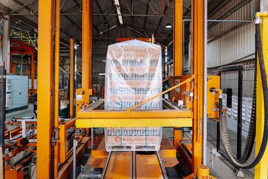
Acceptance tests record three values: peak cases/min at rated product load, glue-tape bond strength on a pull-test rig, and case-squareness on a sampling of 50 consecutive cases with a tolerance of 1.5 mm diagonal variation [S3]. When acceptance fails on mis-folding, the root cause is usually flight-tim
ing rather than mechanical alignment — re-teach the pick-head dwell window against a fresh encoder zero and re-run the dry cycle before any mechanical re-shim is attempted [S3]. Field data from Chinese integrators notes that for related equipment like gland packing pumps and valve gear on the same plant, a linear guide or rack-pinion wear trace is the most common rejection-cause after the 6-month mark, and a similar wear-pattern audit at 1,000 hours is recommended for case packer slides [S2].
Comparison: Manual Drop-Type vs Robotic Manipulator Case Packing
Drop-type case packers suit low-mix, high-volume runs of rigid products at typically 8–15 cases/min, with lower capex and shorter installation lead time but limited flexibility on case size [S2]. Robotic manipulator case packers, by contrast, handle 20–40 cases/min across mixed SKUs and tolerate higher case-format variation, at the cost of longer commissioning, stricter floor-flatness, and a higher spare-parts holding [S2]. The selection rule: choose drop-type when product and case format are frozen, choose manipulator when changeover frequency exceeds two SKU changes per shift [S2].
Limitations and When to Escalate
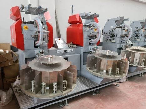
Case packer installation is not a single-technician job once line length exceeds 8 m: above that, a second installer and a rigger are needed for conveyor section lifts, and electrical sign-off must be performed by a licensed electrician with a documented test record [S3]. Do not attempt on-site repair of servo-drive faults — escalate to the OEM with the fault code from the HMI, since field replacement of a servo pack without load-matching risks downstream linear guide pre-load drift [S3]. Warranty coverage is commonly set at 24 months from shipment, but consumables (suction cups, belts, glue nozzles) and any damage traced to a missed maintenance interval are excluded under standard vendor terms [S3].
Trackable next signals to watch: (1) the vendor's published acceptance certificate, which fixes the agreed cycle-time and reject-rate baseline; (2) the 1,000-hour wear audit scheduled for the pick-head crossed-roller guide bearings; (3) the first 6-month servo-drive temperature log, which sets the trend for the next maintenance interval [S3].
See also our earlier report, Machine Vision System Market 2026: $49.7B to $159.2B Trajectory and Spec Map.