Collaborative robots in power and force limiting (PFL) mode run the tool center point (TCP) at no more than 250 mm/s during any operator-interactive state, with peak contact force bounded by the biomechanical limits in ISO/TS 15066 [S4][S6]. The TCP-speed ceiling is a safety function in its own right, implemented in the safety-rated software and required to meet the same SIL or PL rating as the rest of the PFL function [S1].
PFL is one of four collaborative modes defined in ISO 10218-1 (safety-rated monitored stop, hand guiding, speed and separation monitoring, and power and force limiting), and it is the only one that allows a free, unguarded shared workspace between the cobot and the operator. Force is most commonly derived from joint torque measurements or from motor current; alternative designs use a wrist force/torque sensor, base F/T, or skin-type tactile sensing [S2][S8].
How the 250 mm/s TCP limit is actually enforced
The 250 mm/s figure is per axis at the TCP, not at the joint, and it applies only while the cobot is in collaborative state; full-rate industrial motion resumes only when the operator leaves the protected space and a safety-rated monitored stop or re-entry handshake confirms the area is clear [S4][S6]. On Universal Robots platforms this cap is set under the Safety menu, with the cap value itself being a safety-rated parameter that the controller will not exceed, even with the program asking for more [S5].
Most PFL cobots also limit TCP acceleration, not just velocity, because impact force scales with the deceleration at contact; a 50% speed cut can lower impact force by more than 50%, due to the quadratic relationship between velocity and kinetic energy (E = ½mv²) [S3]. For context on how drives upstream enforce such motion caps, see variable speed drive sizing rules used in the cobot's joint servo chain. Joint torque is sampled in the millisecond range and the safety reaction time from contact to stop is typically below 250 ms, matching the stop-time assumption used in ISO/TS 15066 biomechanical limit calculations [S3].
Force and pressure thresholds: ISO/TS 15066 body-region tables
ISO/TS 15066, the technical specification referenced by ISO 10218-1/-2, was built on pain-onset testing of roughly 100 human subjects, with separate maximum permissible values for transient contact (sudden impact) and quasi-static contact (sustained pressure/crush) across 29 body regions [S3]. The standard does not give a single universal "safe force" number; permissible contact force for the hand or fingers is much higher than for the face, neck, or chest, and the allowed value depends on whether the contact is clamped or freely recoiling [S3][S7].
OEMs implement those body-region limits as configurable thresholds, so the same cobot can be run against a relaxed limit when it is working next to a part fixture and a tighter limit when the operator's hands enter the workspace [S9]. Force is the controllable variable; mass and payload are fixed, so reducing acceleration and TCP speed is the only way to keep contact energy below the table values. A useful input to those calculations is the actual contact force reading from a force gauge used during commissioning, which lets the integrator verify the cobot matches its data sheet before sign-off.
Sensor architectures: joint torque, base F/T, and current-based PFL
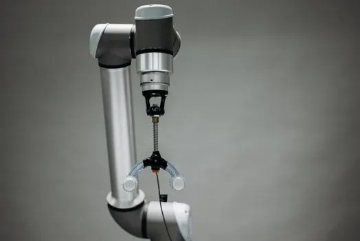
Joint-sensing cobots dominate the PFL market and use either strain-gauge torque sensors in each axis (KUKA LBR iiwa 14 R820) or joint motor current (Universal Robots UR10) to estimate external load; the current method is cheaper but slower and less accurate at low forces, which is why UR pairs it with a separate joint-position model to reject gravity and inertia [S2]. Force-sensor-base designs (FANUC CR-15iA, CR-35iA) place a single F/T sensor at the robot base, which limits resolution to a few newtons and works best on heavier-payload arms where the base sensor can survive the reaction loads [S2]. Inherently safe designs (ABB YuMi) use very low mass and low payload to stay under biomechanical limits even with crude force estimation, while skin-sensing cobots with tactile arrays remain rare in production because the skins wear and the controllers are still slow [S2].
ISO 10218, R15.06-2025, and what the 2025 standards reset actually changed
Until the R15.06-2025 cycle, power and force limiting compliance testing in North America lived in a separate technical specification (ISO/TS 15066) and was treated as guidance rather than a normative test method; R15.06-2025 lifts those PFL test procedures into Part 2 of the standard, making compliance testing for PFL mode mandatory rather than optional [S10]. The stop-time / stopping-distance assumption of ~250 ms that PFL force and pressure calculations rely on is now bound to a documented test method, not a vendor datasheet number, which is a real change for integrators that used to argue from first principles [S3][S10].
Speed and separation monitoring (SSM) and PFL are now the two main options for full workspace sharing: SSM lets the cobot run fast when the operator is far and slows it as they approach, while PFL accepts any operator position and relies on the impact-force ceiling to keep contacts safe [S7]. For machines that switch modes, ISO 10218 also requires that the safety logic, not the application program, enforces the transition, which is why the speed cap is implemented as a safety-rated parameter rather than a setpoint in the task program [S1][S5].
Where the 250 mm/s cap hurts productivity, and the workarounds
A cobot limited to 250 mm/s is roughly 2-5x slower than the same arm in industrial mode, which is fine for machine tending, screwdriving, and small-parts pick-and-place but a hard ceiling for any application with a multi-second move over hundreds of millimetres [S4]. The common workaround is to use the safety-rated monitored stop to fence the operator out with a light curtain or area scanner, run the cobot at full industrial speed in the fenced zone, and drop to the 250 mm/s cap only during the operator-entry handshake [S4][S7].
For pick-and-place and high-mix cells where the operator is always in the workspace, integrators cut cycle time by trimming the move profile (lower acceleration, smoother blends) rather than pushing the TCP speed above the cap; this is also why most weighing force cells that handle small parts in a cobot envelope are tuned for sub-second settling, not high-throughput batching. The trade is fixed by the standard: you cannot get higher TCP speed in PFL without leaving ISO 10218 compliant collaborative operation [S1][S4].
Who PFL is for, and where it is the wrong tool
PFL is the right collaborative mode when the operator must be in the workspace during the cobot's task, when contact is expected (hand-guided teaching, fixtures the human repositions, jigs the human holds), and when the cycle time is set by the operator, not the robot. It is the wrong tool for high-throughput palletising (use a fenced industrial robot), for any cell where the operator only approaches the robot at the end of cycle (use SSM with a faster TCP), and for processes that intrinsically need a sharp tool or high pressure (most metal cutting, heavy welding), where a guarded industrial cell is still the safer default [S2][S4][S7].
For purchasing, the practical selection filter is: payload required, sensitivity of the largest part, and whether the operator is in the workspace during motion. If the answer to all three is "light, light, yes", a joint-current cobot (UR-class) is the cheapest fit; if the answer is "heavy, light, yes", a base F/T cobot (FANUC CR class) is the practical answer; if the answer is "light, sensitive, yes", a joint-torque cobot (KUKA LBR iiwa class) is the right one [S2][S8]. The checking and testing apparatus used at commissioning, including calibrated F/T gauges and a contact-event recorder, is what proves the system actually meets the threshold in the standard, rather than just claiming it.
Field failures and limitations integrators hit in practice
The most common real-world PFL failure mode is not a hard collision but a slow clamp: the cobot traps a hand or finger against a fixture and the quasi-static contact limit is exceeded, which is the case ISO/TS 15066 separates from transient impact [S3][S7]. Joint-torque and current-based cobots both struggle to detect low-speed quasi-static contact because external torque is small relative to friction and gravity model error, which is why some PFL systems add a vision-based volumetric or skin-based envelope as a backup sensor [S2][S8].
Other recurring issues: stop-time drift as the cobot ages, which forces a re-derivation of the safe speed/force/separated-distance budget every service interval; payload changes (end-effector swap, gripper finger replacement) that quietly move the centre of mass and break the gravity model; and floor-flatness problems that the controller cannot see, which is why construction machinery and equipment used to level the cobot base is a real procurement line item, not a courtesy. None of these are solved by raising the TCP speed, because the cap is a function of the contact physics, not the controller's mood [S1][S3].
Sourcing, standards, and what to verify at FAT/SAT
At factory or site acceptance, the documents the integrator should produce are: the risk assessment per ISO 10218-1, the PFL mode validation per ISO 10218-2/-TS 15066 (now mandatory under R15.06-2025), the safety function parameter set (TCP cap, joint limits, stop time, force thresholds) printed from the controller, and a stop-time/force measurement record made with a calibrated F/T gauge on the actual installed arm [S3][S9][S10]. Lamps and light fittings for the cell, including stack lights and the area-scanner indicators, are part of the safety chain and should be listed in the same validation file because they signal the mode transition the operator is relying on.
Trackable signals worth watching in 2026: the move of PFL compliance testing from TS 15066 into ISO 10218-2 under R15.06-2025, which is changing which test reports integrators can accept from OEMs [S10]; the spread of base-mounted F/T cobots into the 20-35 kg class as automotive tier-1s add PFL cells next to existing manual lines; and any update to the 250 mm/s TCP figure itself, which has held since ISO 10218 was first published but is now under review as payload classes and sensing quality improve.
See also our earlier report, Taper bush jacking holes vs tightening holes: function and field test.