
The PU cold box process, introduced by Ashland in 1968, accounts for over 60% of sand core production in Europe and runs a comparable share worldwide [S1]. It is a two-stage operation: compressed-air shooting of a sand plus two-part resin (phenol-formaldehyde P1 and isocyanate P2) into the core box, followed by amine gassing plus air purge to harden the mass before eject [S1].
For process engineers, the four operational sub-steps that matter most are sand fill, amine gassing, post-cure air purge, and core ejection. Each sub-step is set on a cold box core machine by the process control unit, with parameters such as air pressure, shooting time, amine quantity, and curing time stored as recipe values [S1].
Sand Fill and Shooting: Getting the Resin-Coated Mass into the Box
The shooting stage uses shop air in the 4-6 bar range to push the pre-mixed sand-binder mass from the hopper through the shooting head and into the core box, filling through the nozzles before venting through the box vents [S1][S6]. Fill density typically lands in the 1.5-1.7 g/cm³ band for silica sand cores, with sand temperature held between 20-30 °C so the P1/P2 resin stays flowable and does not pre-react in the mixer [S1].
Shooting time, blow pressure, and the vent pattern on the tool together decide whether the box fills uniformly or whether you get soft corners and gas-pocket voids that only show up at ejection [S3]. A consistent shooting recipe also keeps the amine consumption stable in the next sub-step, because under-filled pockets still consume catalyst while over-packed zones restrict gas flow during cure [S1].
For a process reference, a typical cold box amine cure runs the catalyst at roughly 5-8% of the binder mass and shoots on machines such as QuickCore and 3-IN-1 units, with vertical, horizontal, and dual-station configurations all in production [S2]. The recipe layer is what links the shooting stage to the cure stage, and any drift in fill weight shows up as a shift in amine demand on the next cycle [S1].
Amine Gassing: Hardening the Sand-Binder Mass
Once the box is filled, the gassing system (GS) routes a tertiary amine catalyst such as dimethylethylamine (DMEA) or triethylamine (TEA) into the core box, carried by compressed air at roughly 1-2 bar above box back-pressure [S1][S5]. The amine contacts the P1/P2 resin and triggers polyurethane cross-linking, which is what turns the loose fill into a dimensionally stable core in seconds rather than minutes [S1].
Gassing time is the most sensitive recipe parameter. Too short and the core center stays under-cured, showing up as low tensile strength and scrap at ejection. Too long and amine is wasted, the work area amines out, and downstream casting porosity from residual nitrogen rises sharply [S1][S5]. Modern control units meter amine by mass flow and let the operator dial quantity independently of the carrier air pressure, which is a much tighter loop than the older time-based dosing on early cold box core machines [S1].
Process data from production audits also points at carrier-gas dewpoint as a hidden variable. Wet carrier air dilutes the amine, slows the cure front, and can leave a tacky core surface, which then causes sand stick on the ejector pins during the next sub-step [S2]. The amine reclamation patent literature describes carrier-gas drying and closed-loop amine recovery as standard practice on engineered systems [S5].
Air Purge: Clearing Residual Amine Before Eject
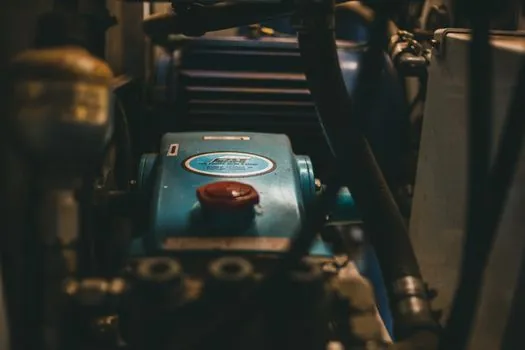
After gassing, the same gassing system switches to clean, dry compressed air to push residual amine vapour out of the core through the vents, which is the purge sub-step [S1][S2]. Purge time is normally 2-4 times the gassing time, with shop air at the same pressure band used for gassing; under-purging is the most common root cause of high amine carry-over into the operator cell [S1][S2].
From a maintenance angle, purging is also a cleaning cycle. Dry air flushing through the manifold and valves clears loose sand, residual binder, and amine aerosols before they polymerise inside the gas distribution block [S2]. On higher-throughput dual-station and QuickCore-style machines, the cure-cycle purge is reinforced with a scheduled solvent flush through the binder and catalyst lines, followed by a heated purge to break down hardened resin before the next production run [S2].
A simple comparison lines the main purge options against three decision criteria that show up on every cell audit: tooling contamination risk, cycle-time overhead, and operator exposure to amine. Dry air purge is low cost and fast, but it does not remove cured resin. Solvent flush removes cured resin but adds cycle time and waste handling. Heated purge cycles sit between the two and are used on high-output hot box core machines and cold box lines where cycle budgets are tight [S2].
Core Eject: Stripping the Part Without Damage
Eject follows once the cure is complete and the purge has cleared the box. Ejector pins, stripper plates, or a combination of both push the cured core out of the box, with cycle time set by the machine control unit rather than the operator [S1][S6]. For thin-walled or high-aspect-ratio cores, the purge step directly affects eject quality: residual amine in the box keeps a thin film of resin soft at the surface, which makes the core drag on the pins and can tear the skin that controls surface finish in the casting [S1][S3].
A well-tuned recipe pairs a short amine quantity with a long-enough purge so the box is dry on the inside before the ejector moves. Production data from simulation-augmented studies links under-purged cores to higher scrap at eject, including soft edges, broken webs, and pin-pull marks that reappear as casting defects after pouring [S1][S3]. A useful sanity check is to weigh the core at eject against the theoretical fill weight, which flags residual moisture and under-cure on the spot [S2].
For lines running 24/7, a separate scheduled ejector-pin maintenance interval is also worth setting. Buildup on the pins acts like a micro-vent, and a sticky pin is one of the leading root causes of cracked cores at ejection on cold box core machines [S2].
Common Process Failures and Where They Originate

Most cold box line stops trace back to one of four sub-steps. In shooting, blow pressure that drifts low causes soft fill and over-shoots amine demand. In gassing, carrier-air dewpoint above -20 °C dilutes the amine and slows the cure front, leaving a tacky core. In purge, a too-short purge window leaves amine in the vents, which then reads as high amine in the cell air and as casting porosity on the metal side [S1][S2].
On the eject side, the most common failure mode is pin stick caused by under-purge plus resin buildup on the pins, which presents as torn core skin or a broken web. Shooting and curing simulation, such as the workflow MAGMA documents for cold box core machines, is now a standard way to map these failure modes back to a specific recipe parameter before they reach the cell [S3].
Two trackable signals to watch on the next audit cycle are: amine consumption per tonne of core (rising trend usually means under-purge), and core weight variance at eject (rising variance usually means shooting drift, since purge does not change mass). Both are easy to pull from the cold box core machine PLC and they are early indicators before scrap shows up on the casting line [S1][S2].
Detailed specification references: cold chamber machine.
For related coverage, see Aluminium Demand 2026: Solar Frames, EVs, and Packaging Pull the Structural Curve.