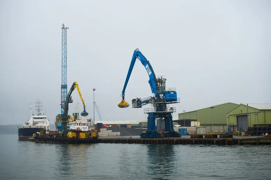
Continuous 360° slewing drives and rack-and-pinion slewing rings rotate the same upper structure on an articulating loader crane, yet they diverge sharply on torque capacity, sealing, and 10-year downtime exposure [S1][S5].
Loader cranes typically reach for slewing diameters in the 1,000–2,000 mm band, with slew drives topping out near 2,000 mm OD and standalone slewing rings available beyond 5,000 mm, which frames the real selection question as torque and duty cycle, not just rotation count [S1][S5].
How each mechanism actually rotates the crane
A slewing bearing handles axial load, radial load, and tilting moment inside one large-diameter raceway, with manufactured diameters spanning 200 mm to over 6,000 mm and over 78,000 large construction cranes worldwide relying on the technology for their 360° rotation [S1]. On a loader crane the same component sits between the rotating column and the truck chassis, with one ring (inner or outer) carrying the integrated gear teeth that the drive pinion meshes with [S2].
Continuous-rotation designs use a worm, planetary, or cycloidal gear inside a sealed housing so the bearing can spin freely past 360° in either direction, while rack-and-pinion slewing keeps the bearing and the drive pinion as separate items that the assembler mounts, aligns, and lubricates in the field [S3][S5]. The integrated unit bolts down as a single component; the rack-and-pinion stack needs a motor, a pinion with module typically 4–25, mounting brackets, a cover, and a customer-designed lube system [S5].
For background on the underlying bearing geometry, see the slewing bearing reference, and for the gear-driven packaged variant the slewing drive entry.
Torque, diameter, and load envelope side by side
Continuous slew drives cover a published envelope of 100–2,000 mm outer diameter, 500–50,000 Nm of torque, and tilt-moment capacity up to 1,000 kNm or higher on the largest models [S5]. The sealed worm gear inside the housing gives inherent self-locking, so the upper structure stays put with no external brake when the motor stops [S5].
Rack-and-pinion slewing rings start at the same 200 mm lower bound but extend past 5,000 mm, which is why most heavy articulating loader cranes and large mobile cranes still use the discrete ring-and-pinion layout for very high torque and tilt loads [S1][S5]. The ring itself does not contain a drive mechanism; the pinion is a small gear on the output shaft of a hydraulic or electric motor that engages the ring teeth, so all torque transmission depends on the pinion module, the contact ratio, and the alignment done at installation [S2][S5].
A useful rule of thumb from the source data: balls give point contact, lower friction, and better multi-directional load behaviour, while rollers give line contact and higher per-element capacity for heavy unidirectional boom loads, which is why most articulating loader-crane slewing rings use a single-row ball or crossed-roller geometry [S1].
Failure rate and 10-year cost comparison
LyraDrive's published benchmark puts the average failure count at 0.5 events for an integrated slew drive against approximately 2 events for a slewing ring and pinion system, a roughly 4× difference that compounds once downtime cost per event is layered on top [S5]. That gap exists because the drive arrives factory-sealed to IP65 or IP66, factory-lubricated with extended-interval grease, and preset for backlash as low as one arcminute on precision models [S5].
A rack-and-pinion stack, by contrast, exposes the open gear mesh, the pinion bearings, and the mounting structure to site dust, wash-down water, and grease loss, so each interface becomes a potential failure point that the operator has to inspect, re-shim, and re-lubricate [S5]. For an articulating loader crane that spends its life on dusty yards, that exposure directly trades against mean time between repairs.
Who each system is actually for
Continuous-rotation slew drives fit solar trackers, small wind turbines, light tower and service cranes, and the smaller end of articulating loader cranes where torque stays inside the 50,000 Nm envelope and the operator values plug-and-play installation over raw diameter [S3][S5]. They are also the right pick when self-locking, low backlash, and IP65/IP66 sealing are written into the crane specification, because those are factory-baked into the integrated unit [S5].
Rack-and-pinion slewing is the better fit for heavy mobile cranes, larger loader cranes, and tower cranes where the upper-structure weight and the lifted load push torque and tilt moment past the slew-drive envelope, and where the OEM or end user already has the assembly infrastructure to align a pinion, manage a separate lubrication circuit, and service the gear mesh in the field [S4][S5]. The flexibility of the modular layout is exactly what lets these machines scale to 5,000+ mm diameter rings [S5].
Selection criteria that actually decide the order
Engineers comparing the two should run the decision on four numbers: required continuous torque, tilt moment, target diameter, and the maintenance regime the fleet can support. Below 50,000 Nm and inside 2,000 mm OD, the integrated slew drive wins on lifecycle cost in published benchmarks; above those thresholds the rack-and-pinion layout becomes the only commercially available option [S5].
For loader cranes that swing through a limited arc only (for example, fold-down stowed position to working arc), the equation tilts further toward the integrated drive because the worm self-lock removes the need for a separate slewing brake, simplifying the hydraulic plumbing [S5]. For machines that must rotate continuously in both directions under heavy load, the rack-and-pinion system with an external slewing brake remains the proven layout, and the loader-crane design literature has tracked this trade-off for over a decade [S6].
Constraints, failure modes, and what the spec cannot hide
Continuous slew drives are constrained at the top end: above roughly 2,000 mm OD and 50,000 Nm, the integrated worm-gear package either does not exist or becomes uneconomical, and that ceiling is set by gear geometry and housing size, not by the bearing inside [S5]. They also lose some efficiency compared with a direct pinion drive because worm gearing introduces sliding losses, which shows up as heat under continuous slow-rotation duty.
Rack-and-pinion systems are constrained by what the installer does at the bench: misalignment between the pinion and the ring concentrates load on a few teeth, accelerates wear, and is the most common root cause of the higher ~2-event failure count the benchmark reports [S5]. Seal design and grease retention on the open gear mesh are the other two weak points, which is why field service intervals on rack-and-pinion slewing are typically measured in months rather than years.
Applicable standards and sourcing checklist
There is no single ISO or EN standard that prescribes "use a slew drive" or "use a rack-and-pinion"; the relevant rules sit inside the loader-crane standard family (EN 12999 for loader cranes) and the general machinery safety regime, with slewing-bearing geometry and material specs commonly aligned to 42CrMo4 ring steel and HRC 55–62 raceway hardness as published industry practice [S1]. For procurement, the checklist should at minimum cover: declared continuous torque (Nm), tilt moment (kNm), OD (mm), IP rating for the drive housing, backlash arcminutes, grease type and re-lube interval, and whether the bearing is ball or roller [S1][S5].
Independent test data points worth tracking into 2027: published failure-rate benchmarks (0.5 vs ≈2 events), the 4.8 → 7.2 billion USD slewing bearing market trajectory, and the rolling-stock count of over 78,000 large construction cranes on slewing ring technology, each of which is a verifiable signal that the technology split is consolidating rather than blurring [S1][S5].
The underlying component specifications are covered under pallet rack.
For related coverage, see BS 8666 shape codes: scheduling, cutting length, and former selection.