
A crawler crane is defined under 29 CFR 1910.180(a)(1) as a rotating superstructure with power plant, operating machinery, and boom, mounted on a base equipped with crawler treads for travel, and its function is to hoist and swing loads at various radii [S1].
That single OSHA definition frames everything below: two physical assemblies, one rotating interface. Lattice-boom machines span a wide capacity band, with current product lines commonly starting near 55 t and scaling through 300 t and 600 t ratings, while super-lift configurations can exceed 3,000 t [S3][S5].
Definition and scope: lower works versus upper works
Engineers partition a crawler crane into a crawler undercarriage (lower structure) and a rotating superstructure (upper structure), coupled through a slewing ring that enables continuous 360° rotation [S2][S4]. The carbody is the central frame on the tracks that supports the slewing bearing and the entire rotating mass above it [S7].
The undercarriage forms the foundation: track frames, track shoes (crawler plates), drive sprockets, idlers, track rollers, carrier rollers and travel motors [S2]. The superstructure above the slew ring carries the lattice boom, A-frame/gantry, boom hoist rope, main and auxiliary winches, counterweight stack, engine and operator cab [S3][S7].
For a crawler crane, OSHA groups this rotating mass under the term "superstructure," while the traveling base is separately called the "base (mounting)" in 29 CFR 1910.180(a)(12) [S1]. The distinction matters in rigging, because the rotating assembly defines the load radius measured from the axis of rotation defined in 29 CFR 1910.180(a)(9) [S1].
Undercarriage components: parts, materials, jobs
Track shoes are forged or cast high-strength steel segments pinned into a continuous chain, and their job is to spread load, generate traction and resist wear on rock, mud or sand [S2][S4]. Track rollers, carrier rollers, idlers and drive sprockets ride inside that chain, supporting shoe weight, guiding the track and engaging the drive motor's torque.
The track frame is the welded structural base that ties the two crawler assemblies to the carbody, engineered to absorb the bending moment transferred during a pick [S2][S4]. A hydraulically extendable track frame is what allows the same machine to widen its footprint and lift more without adding counterweight [S5].
Ground pressure is the design driver: the wide track base lowers kPa on soft soils and is exactly the variable sized in crawler crane track pad width vs ground bearing pressure rules, where bearing capacity and pad area set the safe pick envelope.
Slewing interface: the bearing that ties the two halves together

The slewing ring (or slew ring bearing) sits between the carbody and the upper structure, and it is the single mechanical element that lets the entire superstructure rotate 360° over the undercarriage [S2][S4]. It carries the full vertical load of the upper assembly plus the overturning moment from the lifted load, so its wear is a critical inspection point [S2].
The slewing drive package around the ring typically includes a hydraulic slew motor, a planetary gear reduction and a slewing brake; together they produce controlled swing speed and hold position against wind load [S2]. Because the slew ring is the only path for vertical load, moment and rotation between the two halves, its bolts, gear teeth and raceway hardness dominate the service interval of the whole machine.
Superstructure components: power, lift, balance, control
The superstructure houses the diesel or diesel-electric power plant, hydraulic pumps, the operator cab, the main and auxiliary winches, the counterweight stack and the boom-foot/A-frame rigging [S3][S7]. The lattice boom is a pinned steel-truss assembly that delivers a high strength-to-weight ratio compared to a telescopic boom, which is why heavy-lift machines (300–3,000 t class) almost exclusively run lattice fronts [S3][S5].
Load control on a modern upper works is no longer purely hydraulic: Load Moment Indicators (LMI) and integrated computers continuously monitor load, radius, boom angle, wind speed and ground pressure, and they enforce the rated-capacity chart [S5]. This is the same logic an angle indicator (boom) accessory defined in 29 CFR 1910.180(a)(8) once did mechanically, now done electronically and fused with the LMI cutout [S1][S5].
Counterweight is the rear ballast that balances the lifted load about the axis of rotation, and its mass is selectable per chart, from a base block up to a stacked super-lift tray [S3][S5]. For modularity, the upper works is designed for self-erection so it can be broken into road-trailer-sized sections and re-assembled on site, which has reshaped mobilization economics for heavy lifts [S5].
Options and types: lattice versus telescopic, narrow versus wide track
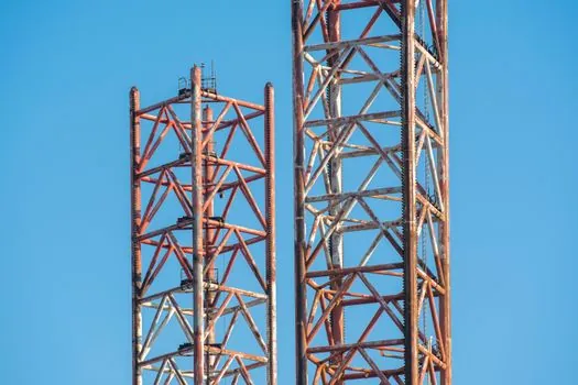
Crawler cranes split into lattice-boom and telescopic-boom types, and the choice is driven by capacity, reach and site mobility. Lattice fronts (Kobelco 7250S, SANY and XCMG heavy-lift models cited in current supplier literature) carry the 80–3,000 t class because each boom section is light for its stiffness [S2][S3].
Track configuration is the second option axis: fixed narrow track frames minimize transport width, while hydraulically extendable (wide) track frames raise stability and rated capacity on outriggers-free picks at the cost of a wider shipping envelope [S2][S5]. Comparison across the four decision criteria a buyer typically weighs:
1) Lift capacity per shipping width: extendable-track lattice wins, because wider shoes raise ground-bearing area and moment stability without extra counterweight [S5]. 2) Pick-and-carry mobility: both configurations travel with load under controlled conditions on firm ground, but the wider track increases rolling resistance [S2]. 3) Boom reach per boom weight: lattice remains the efficient choice above ~80 t because truss sections are lighter per metre of tip height than telescopic sections [S3][S5]. 4) Site assembly time: modular self-erection lattice upper works has compressed mobilization from days to a single shift on current models [S5].
Who it is for, and who should pick a different machine
A lattice-boom crawler crane is the right tool for wind turbine erection, petrochemical module lifts, bridge beam placement, powerplant construction and heavy industrial work where the machine can be on soft or prepared ground and where a long, light boom is needed [S2][S5].
It is the wrong tool for short-cycle, high-mobility taxi work on finished pavement, for indoor plants with low overhead clearance, or for jobs that need a telescopic boom to reach over obstacles without re-positioning, because the lattice boom is a fixed geometry and the tracked undercarriage is not street-legal at speed [S2][S5].
Failure modes, wear points and inspection priorities

On the lower works, the documented wear drivers are track-shoe pin/bushing wear, track-roller flange cracking, idler and sprocket tooth wear, and travel-motor seal failure, all of which shorten undercarriage life on rock [S2][S3]. Carrier-roller and track-roller flat-spotting accelerates when the crane travels long distances with load, which is why OEM service intervals shrink for pick-and-carry duty [S2].
On the upper works, the dominant failure modes are slew-ring raceway brinelling, slew-drive gear-tooth spalling, hoist-drum rope spooling problems, boom-pin bearing wear and counterweight bolt loosening; each is a documented inspection gate before any heavy pick [S2][S5]. The OSHA-recognized standard governing crawler locomotive and truck cranes is 29 CFR 1910.180, which defines every component named above and sets the inspection and operational rules for the assembled machine [S1][S6].
Standards, sourcing and procurement references
U.S. crawler crane assembly, inspection and operation fall under 29 CFR 1910.180, with the component vocabulary (base, boom, boom hoist, cab, counterweight, axis of rotation, angle indicator) defined in §1910.180(a) [S1][S6]. Component-level design typically references ANSI/ASME B30.5 for mobile and locomotive cranes, though the OSHA rule itself does not pin a specific revision [S1].
For sourcing, the undercarriage is overwhelmingly wear-and-tear parts (shoes, rollers, idlers, sprockets, travel motors), and aftermarket supply is mature from both OEM channels and independent suppliers such as the peersparts catalog referenced in component guides [S4]. Superstructure spares (slew ring, slew drive, winch, LMI computer, boom sections) are more OEM-controlled and represent the higher-value replacement decision on a 10–15-year-old machine [S2][S5].
Operators should spec the undercarriage against the heaviest planned pick (track-pad area and bearing pressure), the superstructure against the longest planned radius (boom length, counterweight, LMI chart), and treat the slew ring as the lifetime component that ties both decisions together [S2][S4][S5].
Trackable signals to watch through the rest of 2026: OEM releases of larger diesel-electric super-lift crawlers above the 3,000 t class, and wider hydraulic extendable track frames entering the 100–300 t segment as modular self-erection spreads from heavy-lift into mid-capacity machines [S5].
The underlying component specifications are covered under lamps and light fittings.