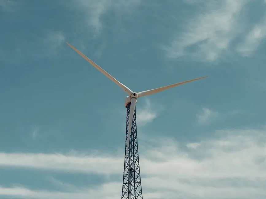
A digital twin for wind turbine blade production is a live, time-synced model of the manufacturing process, the blade geometry, and the in-service structure, fed by layup, infusion, cure, NDT, and field sensor streams rather than a single static FEA file [S1][S3]. The 2024 review by Leon-Medina et al. frames the technology as a multi-domain enabler across production, installation, and maintenance, with explicit attention to rotor-blade components [S1].
On a modern 80–100 m blade, the data spine now includes resin temperature, exotherm peak, fibre areal weight, infusate front position, ultrasonic or thermographic NDT, and field MEMS acoustic/aerodynamic feeds, aggregated in a SCADA/IoT platform that drives both the in-process twin and the in-service twin [S2][S3][S4]. The same architecture is being repurposed inside blade factories: Ewan Norris's Aura CDT PhD project at the University of Hull is building a blade-factory digital twin that records and analyses production parameters so that defects can be traced to specific process deviations rather than to downstream inspection results [S6].
In-process digital twin: layup, infusion, and cure
The in-process stage of a blade digital twin maps the actual part to its nominal model in near real time. Resin thermocouples, dielectric cure sensors, and oven-zone profiles feed a process state estimator that compares the part to its golden-batch trajectory, and layup sensors (laser profilometry, layup imaging) feed the geometry branch of the twin [S1][S3]. The 2024 Frontiers in Energy Research paper on the Aerosense digital twin describes the same paradigm, with low-cost MEMS sensors on the blade, cloud aggregation, and a 'Digital Shadow' twin that runs simulation and prediction on top of the measured data stream rather than replacing it [S3].
Where the hull factory twin goes further is the explicit coupling between production data and part-level QC: by tagging every layup ply, vacuum-bag step, and cure ramp with a part serial number, deviations can be replayed during a future failure investigation. The benefit numbers reported for in-service twins are the proxy for why this matters: shifting from reactive to predictive maintenance is documented at roughly 11% lower O&M cost in wind farm studies, with asset dashboard tools cutting field inspections by 60% and repair lead time by 85% [S2].
In-service digital twin: MEMS, acoustic emission, and structural health
The in-service stage of the blade digital twin is the part most often discussed in the literature. The Aerosense system uses flush-mounted MEMS microphones and aerodynamic pressure sensors to capture aero-acoustic and load data on operating blades, then mirrors it to a cloud twin for anomaly detection and predictive modelling [S3]. The earlier DanAERO campaign, which instrumented a 2 MW rotor blade with 50 flush-mounted microphones, is the reference data set that justifies the current low-cost MEMS approach, since the aero-acoustic signature carries three-dimensional flow information that blade-only strain gauges miss [S3].
For offshore wind, the sensor stack is typically augmented with vibration, temperature, and rotor-shaft alignment channels, and the twin watches for known failure precursors: blade fatigue or erosion, rotor-shaft misalignment, and gearbox overheating or wear [S4]. GE Renewable Energy's published offshore-wind digital-twin work uses this pattern to schedule maintenance into weather windows rather than reacting to alarms, which is the direct value case for the digital twin once it spans both factory and field [S4].
Comparison of three blade-twin architectures
Process engineers evaluating a blade-factory or blade-service twin will typically choose between three architectural patterns documented in the source material. The table below lines them up against the criteria that actually drive project cost and risk. [S3]
Option A, a 'Digital Shadow' (one-way data flow from physical to virtual, no automatic control, e.g. Aerosense), is the lowest-risk entry: it sits on top of existing SCADA and MEMS feeds, runs prediction in the cloud, and integrates with a pressure transmitter and vibration sensor layer on the nacelle [S3]. Option B, a closed-loop production twin used in factory trials such as the Hull Aura CDT project, couples layup and cure sensors back into the MES and adjusts cure ramp setpoints, but it requires the higher sensor density and data-quality controls that come with a controlled factory environment [S6]. Option C, a full bidirectional twin that drives design iteration (the Siemens Gamesa and GE Renewable Energy pattern), uses field twin data to update the next-generation blade design, including carbon-fibre layup choices, and demands the strongest data governance [S4].
For most blade producers the practical path is A first, then B once the data pipeline is stable, with C reserved for OEMs that run their own fleets at scale. Across all three, the flow meter class is the same as for any closed-loop process: resin and coolant flow measurement at the layup station follow the same selection logic as in any composite infusion line.
What it is, and what it is not
A blade digital twin is NOT a single FEA model re-run every night, and it is NOT a SCADA dashboard. The 2024 Leon-Medina review defines it by two properties: 'duality' (a paired virtual and physical entity) and 'strong similarity' (the virtual side is kept current against the physical side through continuous data exchange), with the in-service and in-process twins sharing the same data spine but differing in update rate and decision authority [S1]. The Frontiers paper makes the same point operationally: the Aerosense twin is explicitly a 'Digital Shadow' rather than a full bidirectional twin, because not every monitoring use case justifies the cost and risk of closing the loop [S3].
It is FOR OEM process engineers who need defect traceability per part serial number, for operations teams running offshore fleets where each avoided vessel visit is a significant cost, and for blade-design teams looking to retire the older build-and-break prototype loop. It is NOT for plants that have not yet instrumented layup and cure at a level that produces a usable golden-batch record: the value of the twin is bounded by the quality of the input data, and the source material is consistent on this point [S1][S3][S6].
Sensor and data pipeline: what gets measured, at what rate
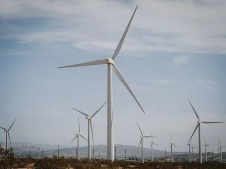
The practical sensor stack for a blade digital twin is built from three blocks. First, the in-process block: resin and oven-zone thermocouples, dielectric cure sensors, and infusion-line flow or vacuum transducers, typically sampled at 1–10 Hz and aligned to part serial number [S1][S6]. Second, the NDT block: ultrasonic C-scan, thermography, or CT, run at defined inspection gates and tagged to the same serial number so the twin can correlate a defect location to the layup and cure record that produced it [S1]. Third, the in-service block: MEMS acoustic and pressure sensors, strain gauges, vibration channels, and standard nacelle sensors, streamed into the cloud twin at lower rates (often 1–100 Hz depending on channel) for aero-acoustic and load monitoring [S3][S4].
The same instrumentation that feeds the blade twin also feeds the rest of the nacelle: vibration, temperature, and rotor-shaft alignment are already standard inputs to a digital panel meter on the operator HMI, and the digital multimeter remains the field engineer's first-line tool for loop checks during commissioning. The digital twin adds a layer on top, not a replacement for these instruments.
Standards, failure modes, and known limits
The source material is explicit about what the blade digital twin does not yet do well. The Frontiers paper notes that, despite increasing demand, the number of publications on rotor-blade aerodynamic monitoring is still small, and the DanAERO and IEA Wind Task 47 programmes are explicitly framed as filling a gap rather than reporting a mature practice [S3]. The Leon-Medina review highlights that two implementations of a 'digital twin' may share few or no technological solutions, which means the term is closer to a design pattern than a specification [S1].
Known failure modes for a blade twin are the usual ones for any sensor-driven system: sensor drift on resin thermocouples, MEMS microphone calibration drift in field conditions, and the simpler problem of data alignment when the same blade moves between factory MES, NDT database, and SCADA without a shared part key. The Hull Aura CDT project is, in effect, a response to this last point, since the research goal is to record production parameters with a part-level identifier so that field failures can be traced back to a specific process deviation [S6]. For offshore fleets the weather-window constraint remains a real limit: a digital twin can flag a fault, but the maintenance crew still needs a vessel slot, which is why GE's published approach uses the twin to schedule, not to dispatch, the intervention [S4].
What to track next
Two signals are worth watching through the rest of 2026. First, the IEA Wind Task 47 programme on aerodynamic measurements of megawatt-scale turbines, which is the most credible cross-OEM venue for shared rotor-blade monitoring data and the place where a common data schema for blade twins is most likely to land [S3]. Second, factory-side implementations of the Hull Aura CDT pattern, since the part-level traceability work is the missing link between the in-service twin literature and the production-side cost case [S6]. A useful verification node is whether the 1,100 GW of new wind capacity projected by 2030 starts to be quoted with O&M delta figures attributable specifically to blade-twin programmes, rather than to wind-farm digitalization in general [S2][S5].
Background reading: AC Torque Motor Continuous Stall Rating for Winding Tension Control.