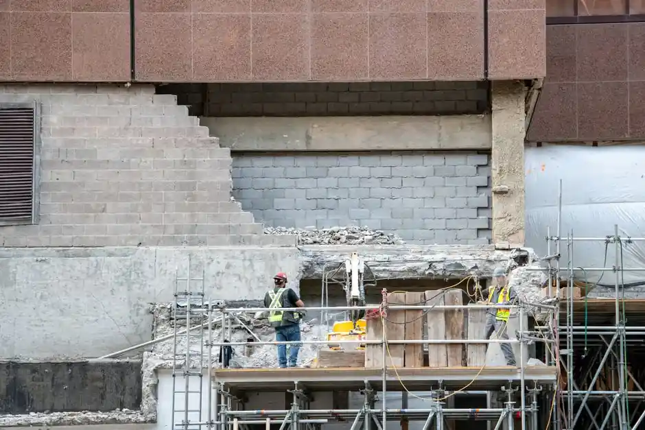
A dynamic compactor is the rig system that densifies loose demolition fill by repeatedly dropping a heavy pounder from a crawler-crane boom, treating soil already in place to depths of 8-12 m without excavation, and it is specified separately from surface rollers or shield machines [S5]. On demolition projects where a basement, tank, or structure has been removed and the void backfilled with mixed CDW, the engineer must match tamper mass, drop height, and grid spacing to the target depth and to whether the fill is free-draining granular or fines-rich.
The 2026 Soils and Foundations paper by Zhang et al. gives the first laboratory-quantified stopping criteria for CDW tamping: at single-drop energies of 2000, 4000, 6000, and 8000 kN·m, the recommended stopping compaction counts are 9, 6, 4, and 4 drops respectively, and the resulting settlement already captures 82-98% of total compaction settlement [S1]. That single data set is the most useful 2026 reference for procurement engineers writing trial-p compaction (TPC) acceptance clauses on a demolition reuse job.
Energy Tiers, Pounder Mass, and the Menard Depth Relation
Improvement depth follows the Menard relation D = n · √(W·H), where D is in metres, W is pounder mass in tonnes, H is drop height in metres, and n is an empirical coefficient usually taken near 0.3-0.5 for granular fills [S5]. A 15 t tamper at 20 m drop, giving 3000 kN·m per blow, typically improves granular soils to 8-12 m depth over 3-6 passes on a 5-8 m grid, while 30-40 t units at port and airfield sites push depth past 15 m [S4]. The trade-off inside the heavy end is weight-per-drop versus drop height: heavier weights with lower drop give controlled deep densification, lighter weights with higher drop give broader but shallower energy transfer [S7].
For demolition-fill reuse the practical range sits in the 5-40 t tamper / 10-25 m drop band catalogued by Chinese OEM Anhui Hefei plants, with the gasoline-driven reversible plate models reserved for trench backfill rather than the bulk fill that follows a structural demolition [S4]. Buyers quoting a USD 1,000,000-1,500,000 class heavy impact-rammer rig should confirm the tamper mass, the free-fall winch single-line release, and the pounder base shape, flat for granular, domed for crater control on cohesive-rubble mixes [S7].
Soil Match: What Compacts and What Fails
Dynamic compaction only works in free-draining granular soils: clean sand, gravel, crushed rock, and well-graded CDW with low fines; high fines content or a high water table makes the impact pressure dissipate without grain rearrangement, and the technique fails [S4]. Saturated soft clay and peat are not densifiable by impact and usually require replacement with a stone-column or stiff-pier composite instead, while the 2026 PSDC (Punching and Squeezing Dynamic Compaction) study in Soils and Foundations confirms that composite piers do form in clay-gravel mixtures under combined hammer geometry and dynamic response [S1]. For a demolition backfill that contains rebar-studded concrete chunks, pre-crushing to minus 300 mm is normal practice before tamping, otherwise stress concentration on a single rebar rod will punch a crater rather than densify the matrix.
Conplant's compaction matrix lines up the realistic alternatives on a demolition site: vibratory smooth-drum rollers cover 0.3-0.6 m per lift and dominate granular subgrade and asphalt work, but they cannot reach the 8-12 m that dynamic compaction hits, and they are not effective on saturated clay [S3]. A dynamic compactor is therefore the right primary tool for a basement-replacement fill thicker than about 3 m, and vibratory or static rollers handle the surface 0.3-0.6 m lift closure after the last tamping pass.
Demolition-Project Decision Gates vs Shield Machines and Rollers
On a heavy-civil demolition site the dynamic compactor is competing for scope against a shield machine only on a transport-infrastructure job, and the two almost never win the same package: the shield bores a lined tunnel and produces muck, the compactor pounds the surface to push a granular layer past refusal and produces no spoil [S4]. Direction of work, depth of effect, ground type, and output unit (mm advance versus kN·m per drop) cleanly separate the two, so procurement should not let a contractor substitute one for the other in a method statement.
For demolition-fills that a roller cannot reach, a pile driver is sometimes mis-specified as an alternative; it is not. A pile driver installs a discrete element into the ground, while a dynamic compactor treats the soil mass in place over a 5-8 m grid. Where a demolition contractor also needs to lift and clear the slab, the right companion machine is a crawler crane sized for the heaviest single pick, not a piling rig. For the building-clearance and material-handling side, the forklift for demolition selection math is similarly grounded in ground pressure and load-center, not in lift height alone.
Comparison: Dynamic Compactor vs Vibratory Roller vs Static Roller on a CDW Fill
For procurement engineers writing a single comparison table in the method statement, the four governing criteria are depth of effect, soil type, output unit, and vibration footprint. A dynamic compactor reaches 8-12 m per pass sequence at 2000-8000 kN·m per drop and works only on free-draining granular or well-graded CDW, producing refusal criteria in drops per point rather than in m²/h, with significant but short-duration ground vibration that can be mitigated by 50-100 m standoff from sensitive structures [S5]. A vibratory smooth-drum roller covers 0.3-0.6 m per lift on granular soils and asphalt at tens of m²/h, with continuous but lower-amplitude vibration, and a static roller is limited to roughly 0.15-0.3 m per lift on cohesive soils with negligible vibration [S3].
That is the most defensible pass-count column to insert into a TPC specification on a 2026 demolition reuse contract.
Standards, Specs, and Acceptance Criteria
Design references for dynamic compaction on demolition work draw on FHWA Geotechnical Engineering Circular No. 1 (Lukas, 1995), the Menard and Broise (1975) depth relation, ASTM D4914 for in-place density verification, and China JGJ 79-2012 for ground-treatment provisions, all four of which a dynamic compactor specification should cite by clause number rather than as a generic reference [S5]. For project-side productivity benchmarks, Volvo's vibratory-drum guidance on impact spacing of 10-14 impacts per foot and centrifugal force as a function of (mass × radius of eccentricity) × frequency² is a useful cross-check for the surface-closure roller pass that follows tamping [S2].
On demolition sites with adjacent structures, peak particle velocity (PPV) at the nearest foundation is the controlling vibration limit and typically caps at 25 mm/s for residential and 50 mm/s for industrial receptors, with trial tamping used to fix the pounder mass and drop height before the production grid is locked. Buyers should also require the OEM to publish a tamper-mass tolerance, a free-fall release certificate, and a base-stress rating, since the same crane can be re-rated from 15 t / 25 m to 25 t / 15 m with a different rigging, and the resulting depth and PPV change non-linearly with the product W·H.
Limitations, Failure Modes, and What Dynamic Compaction Cannot Fix
Dynamic compaction is not a remediation tool for contaminated demolition fill, not a replacement for stone columns in saturated clay, and not a substitute for a demolition hammer on the structural side, where breaking concrete before backfill remains a separate operation that the high-energy impact-rammer variants can combine with tamping only on thin slabs. The PSDC follow-on study in Soils and Foundations 2026 confirms that composite piers form under punching-and-squeezing hammer geometry, but this is still a fill-reinforcement method, not a way to remediate soft clay below a demolition footprint [S1].
Failure modes seen on real demolition-reuse jobs include crater blow-out on saturated silty CDW (fines content above about 15-20% by mass), excessive PPV complaints from neighbours, and under-treated depth where the operator drops a lighter pounder from a higher hook to chase production rate, the result is shallower effective depth and a higher relative crushing rate on the upper 2-3 m, leaving the 5-10 m zone under-densified. The fix in every documented case is to revert to the W·H pair from the trial-p compaction and to enforce the 4-9 drop stopping counts above.
Track the 2026-09 publication of the PSDC pier-formation paper in Soils and Foundations Volume 66, Issue 2, since it is the second CDW-relevant 2026 paper in that journal and will likely be cited in 2027 demolition-fill specifications alongside the Zhang et al. stopping-criteria study. Watch also for OEM-published tamper-base stress curves on Jiangsu-built 30-40 t units, because the USD 1,000,000-1,500,000 price band has narrowed the supplier list to a handful of plants whose published base-stress ratings now determine the safe grid spacing on port and airport demolition reuse work [S7].
For the relevant spec sheets and selection criteria, see dynamic balancing machine.