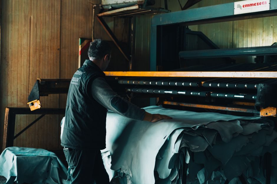
Production volumes are scaling across in-house OEM lines (Ford's 53-year-old Van Dyke Transmission Plant in Sterling Heights, MI, retooled for $150 million) and contract suppliers, with a typical e-motor containing roughly 20 moving parts versus 200+ in an internal combustion engine [S3]. For a primer on the underlying AC motor topology most EV traction units derive from, see the encyclopedia entry.
Subassembly Breakdown and Bill of Materials
An EV traction motor typically breaks into a rotor (shaft + magnets or reluctance iron), a stator (laminated steel core + copper windings), a housing/inverter integration, and a motor control unit [S3].
Permanent-magnet motors still dominate, but rare-earth-free alternatives (externally excited synchronous machines, ferrite-assisted synchronous reluctance) are gaining R&D weight precisely because magnet material cost and supply chain risk have made the magnet bill the single most volatile line item on the BOM [S6]. The rotor-shaft press-fit, magnet insertion, and balancing operations are the tightest-tolerance stations on the line, which is why ABB Robotics has focused flexible robotics cells on rotor assembly rather than stator [S3].
Winding Technologies Compared
Three winding approaches are running in serial production as of 2026: (1) random round-wire winding, the cheapest and most flexible but limited to ~45% slot fill; (2) hairpin/wave-wound rectangular bar, used by GM Ultium, BMW, Volkswagen, BorgWarner, ZF, and Tesla, giving 60–70% slot fill at the cost of a dedicated winding and laser-welding station set; and (3) continuous wave-wound ribbon, used in some axial-flux architectures where the "short" axial path lets a single bent conductor fill the slot [S3][S6].
Trade-off, in plain numbers: hairpin lines cost roughly 2–3× the capex of a round-wire line of the same throughput, but deliver 8–15% more continuous torque density and measurably better thermal conductivity through the end-windings because the rectangular cross-section presses more copper against the lamination stack [S6]. For OEMs below ~80,000 units/year, round-wire often still wins on total cost of ownership; above that threshold, hairpin amortizes inside the first product cycle. For the underlying electromagnetic principle, the linear motor entry in the encyclopedia gives a complementary geometry reference.
Axial-Flux Versus Radial-Flux Architecture
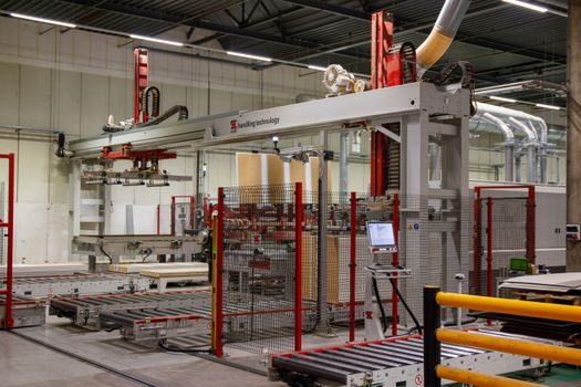
Axial-flux motors—such as the Saietta Group unit shown in industry coverage—run the magnetic flux path parallel to the rotor axis rather than radially, which lets the designer shorten the magnetic circuit and stack two rotor discs against a single stator disc, cutting active mass by 30–40% at equal torque [S3]. The trade-off is manufacturing: axial-flux stators are large flat discs, not cylindrical stacks, so the lamination and winding stations are non-standard and most suppliers still use short, hand-loaded cells rather than fully automated lines.
Radial-flux remains the default because it reuses the stator/rotor tooling ecosystem originally built for industrial AC motor production; axial-flux is currently positioned as a niche for high-torque-density motorcycle, light-commercial, and in-wheel applications where the disc form factor can be packaged around the wheel hub rather than underhood [S3][S4]. Saietta and a small cluster of European startups are the visible named players; major OEM serial-production axial-flux programs are limited as of mid-2026.
Stator Assembly Process Flow
The stator sub-line, as a sequence of operations: blanking of electrical-steel coils into 0.25–0.35 mm laminations, interlock or laser-welded stacking to a target stack height (typically 50–150 mm for automotive traction), inter-turn insulation paper insertion, winding (round-wire via needle or hairpin via inserter and twisting), end-winding forming and laser welding of hairpin joints, impregnation (dip or VPI — vacuum pressure impregnation), and finally stator testing (Hi-Pot, surge, partial discharge) [S6].
On a hairpin line, the laser-welding station is the bottleneck: each hairpin end has to be welded to its neighbour in a defined sequence, with typical cycle-time targets of 60–90 seconds per stator for a ~250 mm outer-diameter automotive unit [S6]. THORS and similar training organisations now market dedicated traction-motor stator assembly courses precisely because the hairpin sub-line is new to most suppliers migrating from industrial-motor production. For perspective on a related but distinct electromagnetic device family, the hydraulic motor encyclopedia page sets a useful contrast on torque density per unit mass.
Rotor, Body Assembly, and EOL Test
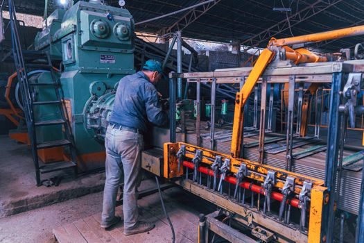
Rotor stations cover magnet insertion (for PMSM), shaft press-fit, magnet-to-shaft keying or sleeve bonding, and dynamic balancing—typically to G2.5 grade at 1500 rpm reference speed for passenger-car units [S3][S6]. Body assembly then marries the rotor into the stator within the housing, bolts the inverter power stage (IGBT or SiC MOSFET three-phase bridge) to the housing or to a separate junction box, routes the resolver/encoder and phase cables, and fills the housing with transmission oil or a glycol-water jacket for direct stator cooling.
End-of-line test cells measure back-EMF constant (Ke, in V·sec/rad), phase-to-phase resistance, inductance (Ld, Lq), insulation resistance at 1 kV DC, partial discharge onset voltage, and a no-load spin to rated speed (often 15,000–20,000 rpm for 800 V-class passenger-car units). The additive manufacturing entry in the encyclopedia documents how 3D-printed copper windings and hairpin cooling jackets are now being piloted to replace bundled copper and machined aluminium sleeves on selected prototype lines.
Standards, Sourcing, and Supplier Landscape
EV traction motors are not governed by a single dedicated product standard; the typical compliance stack pulls in IEC 60034 (rotating electrical machines base standard), ISO 1940 (balance quality), IEC 60204 (drive system electrical safety), ISO 26262 (functional safety at vehicle level), and—for 800 V architectures—AEC-Q100/Q101 for the inverter die [S2][S3]. The Chinese GB/T 47025-2026 standard published 2026-01-28 covers ADAS simulation testing for connected vehicles, not traction motor production, but the autonomous-drive and traction-motor lines now share much of the same end-of-line instrumentation in Tier-1 plants [S1].
For engineers sourcing components, "EV Traction Motors" is now a discrete product category on industrial parametric search portals, filtering on motor type, torque, speed, power, and vehicle type, alongside related categories like EV ECUs, EV fuses, and motor driver ICs [S2]. The visible named manufacturing cluster as of 2026 includes BMW, Ford (Van Dyke), GM (Ultium Drive, three interchangeable motors in one family), Volvo (Skövde, Sweden), Volkswagen, ZF Friedrichshafen, BorgWarner, ABB Robotics (line integrator), and Saietta Group (axial-flux specialist), with Tesla the largest single captive producer [S3]. Among adjacent electrified-component flows, see our process walkthrough of battery cell manufacturing in 2026 and the battery pack assembly line map for the rest of the powertrain.
Trackable signals for the next 12 months: hairpin line capex announcements above the 80,000-unit/year threshold, the first 800 V SiC-inverter integrated housing in serial production, and the disclosure of a third OEM adopting axial-flux in a passenger-car program after Saietta's motorcycle wins [S3].