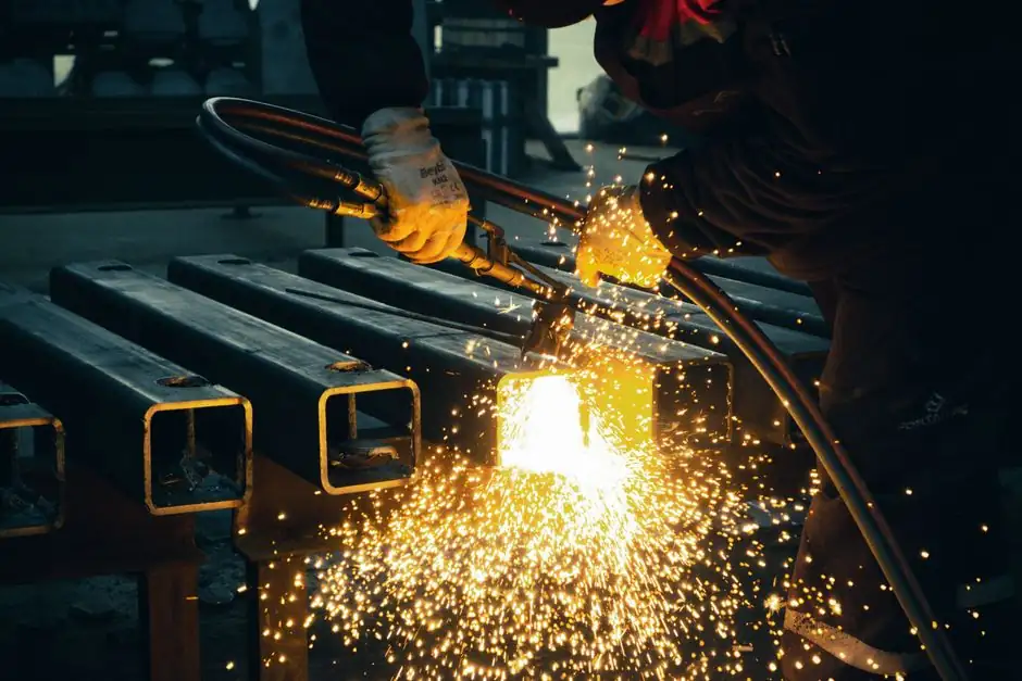
ESW is specified when a single vertical pass must join steel from 19 mm to multi-hundred-millimetre box-column plate, with no arc flare-up and no interpass stops, per the Welding Handbook overview [S3].
Selection for steel construction turns on four physical facts: the joint must be vertical (max 15° from vertical), the parent material is limited to carbon or low-alloy steel, the slag pool is held by water-cooled copper shoes, and the run cannot be interrupted once started [S3]. For a process engineer mapping equipment to project scope, these constraints define both the spec map and the reject list.
Process mechanics and the 19 mm floor
ESW starts as a struck arc, then transitions to resistive heating through a molten slag bath once the flux melts and conductivity rises; the arc is effectively short-circuited by the conductive slag, and current is carried slag-to-workpiece for the rest of the pass [S3]. That single transition is why the process is restricted to the vertical or near-vertical position (slope ≤ 15°) and why a continuous run is non-negotiable.
Minimum parent-metal thickness is 19 mm (¾ in.); the process is also used on very thick plate from 40 mm upward, with one or more filler wires and head weaving at the upper end of the thickness range [S3]. For typical box-column diaphragm work in Japanese high-rise construction, this 19 mm floor is the gating spec that decides whether ESW is even on the table versus stud welding or arc welding alternatives [S2].
Where ESW wins on a steel-construction project
ESW is chosen where the productivity delta over multi-pass arc welding is largest: built-up box columns with interior diaphragm plates, thick-plate bridge girders, and other civil/structural assemblies where joint volume, not joint count, drives the schedule [S1][S2]. Per the process overview, the benefits stack as: high deposition rate, low joint-prep cost, single pass regardless of thickness, minimal angular distortion on butt joints, low transverse shrinkage, and little risk of hydrogen embrittlement [S3].
The Harada et al. state-of-the-art review frames the application window precisely: ESW for built-up box-column interior diaphragms in Japanese high-rise steel buildings is the canonical use, with active design guidance aimed at preventing brittle fracture under seismic loading [S2]. That seismic context is the reason HAZ toughness is not optional, and it is also the reason selection for impact-critical members has narrowed in modern practice.
Where ESW is the wrong tool
ESW is the wrong process when impact toughness in the HAZ is a code requirement: the high heat input drives slow cooling, which allows substantial grain growth, and the base material will then have insufficient HAZ toughness if the joint spec demands Charpy impact values [S3]. Selection must screen out any member flagged for low-temperature service, seismic demand critical (SDC-D and above in U.S. practice, or the equivalent Japanese high-ductility member class), or fracture-critical bridge designation.
It is also the wrong process for thin plate (under 19 mm), for any joint that cannot be guaranteed continuous start-to-finish, and for stainless, quenched-and-tempered, or high-alloy steels, because the process is restricted to carbon and low-alloy steels [S3]. When the run must be paused, or the joint has to be re-entered, switch to multi-pass submerged-arc or TIG approaches instead.
Equipment selection map: head type, wire count, shoe cooling
Selection for steel construction is driven by three machine-level decisions: fixed-head versus traveling-head, single-wire versus multi-wire (or consumable-guide tube), and water-cooled copper shoe arrangement (fixed versus traveling with the head) [S3]. A fixed head with a consumable guide tube can produce welds up to roughly one metre long because the tube length sets the weld length; the tube melts into the joint as filler and as a slag contributor, which keeps slag-pool depth constant [S3].
For typical box-column diaphragm work in the 19-50 mm range, single-wire traveling heads are common; for very thick sections, multi-wire heads with weaving are specified because a single wire cannot keep the slag pool molten across the full plate width [S3]. The comparison for the specifier is direct: thicker plate and longer passes push selection toward traveling multi-wire heads with high-deposition power sources, while shorter interior-diaphragm welds in the 19-40 mm band are well-served by simpler single-wire or consumable-guide fixed heads. A project that also runs construction tools for rebar prep or diaphragm fit-up should plan shared 380-440 V three-phase feed and cooling-water supply at every ESW station, not just at the welder itself.
Comparison: ESW versus alternative thick-plate processes
Against multi-pass submerged-arc welding (SAW), ESW wins on deposition rate, joint-prep cost, and distortion control; SAW wins on HAZ toughness, ability to pause and re-enter, and applicability to non-vertical joints [S1][S3]. Against electrogas welding (EGW), ESW is generally thicker-plate oriented (19 mm and up) and uses a stationary slag bath versus EGW's externally shielded gas; EGW is usually preferred in the 10-30 mm range where the joint can still be done in one pass without a deep slag pool.
For shear-stud or diaphragm-to-face attachment, stud welding is the standard alternative, with different equipment class and no molten slag bath. On a steel-construction jobsite that also runs heavy rebar prep, the rebar bender selection guide is a useful cross-reference for matching bar diameter to bending code radius when box-column cage work is in scope.
Quality control and brittle-fracture risk
Brittle-fracture control is the single biggest design risk for ESW in modern seismic practice, and the Harada review explicitly recommends joint design and fabrication rules to mitigate it [S2]. The mechanism is well documented: high heat input, slow cooling, coarse prior-austenite grains in the HAZ, and low Charpy values versus the base plate [S3]. Mitigations include specifying lower heat-input ESW variants, restricting ESW to non-fracture-critical members, and applying weld toughness qualification testing at the procedure-qualification step rather than relying on production coupons.
NDT on ESW joints is typically UT plus RT: the coarse columnar grain of the as-deposited weld scatters ultrasonic shear waves, so RT is often required in addition to confirm lack of slag inclusions, porosity, or sidewall fusion defects. For any project mixing ESW with on-site stud or stud-welder attachment of secondary members, plan the UT/RT window before erection so access is preserved, not after the diaphragm is buried.
Sourcing, power, and site-fit checklist
Specifying the right electroslag pressure welder for a steel-construction project is a four-point check. First, parent material: carbon or low-alloy steel only, 19 mm minimum thickness. Second, joint geometry: vertical or within 15° of vertical, continuous run, no planned interruption. Third, machine class: single-wire traveling head for 19-50 mm diaphragm work, multi-wire weaving head for thicker box-column walls, consumable-guide fixed head for short sub-one-metre passes where a fixed station simplifies alignment. Fourth, site feed: 380-440 V three-phase, dedicated cooling-water circuit for the copper shoes, and segregated laydown for the granulated flux that becomes the slag bath [S3].
Trackable signals to watch over the next procurement cycle: revision of Japanese design guidance on ESW for high-ductility seismic members following the Harada review, and any project that pushes ESW above the 100 mm single-pass wall while still meeting HAZ Charpy spec [S2]. On a mixed jobsite, coordinate ESW stations with construction machinery and equipment layout so the cooling-water and three-phase feeds do not collide with crane paths, and confirm any electroslag pressure welder rental includes the shoe-cooling skid, not just the power source.