
Emergency stop circuits in 2026 industrial builds are still pinned to three baseline documents: ISO 13850 for the emergency stop function itself, IEC 60204-1 for machine electrical equipment, and NFPA 79 for U.S. industrial machinery, with stop categories limited to 0 and 1 by those standards (CSA C22.2 No. 301 also permits Category 2) [S2][S4].
Specifying the right emergency stop is a risk-assessment outcome, not a checkbox: the chosen category, performance level (PL), contact-block topology, and actuator geometry all have to align with the hazard severity, the frequency of exposure, and the possibility of avoidance, otherwise the device becomes a labelled placebo rather than a protective measure [S1][S5].
Stop Categories 0, 1, and Where Each Fits
IEC 60204-1 stop categories describe the control-function outcome, not the device, and only Category 0 (uncontrolled stop, immediate power removal) and Category 1 (controlled stop with power retained until the stop is achieved) are permitted as emergency stop functions in ISO 13850 and NFPA 79 [S2][S4].
Category 0 is the right call for hazards where any controlled-deceleration ramp is itself dangerous: a horizontal stamping press, a guarded robot cell with a pinch point, or a conveyor drive whose brake torque is part of the safety case. Category 1 is preferred where removing power immediately would create a worse hazard than a controlled stop, for example a vertical axis holding a suspended load, a high-inertia centrifuge, or a servo-driven glass-handling robot where the suction-cup vacuum must stay live while the arm is being brought to a safe state [S5]. Categories 2 (power retained, only the hazardous element is shut down) is outside the strict ISO 13850 emergency stop definition and is generally reserved for functional-stop or safety-rated stop functions, not for the hard-wired E-stop pushbutton [S2][S4].
Performance Level, SIL, and Risk-Graph Inputs
Emergency stop devices are usually required to meet at least PL c under ISO 13849-1, with Category 1 hard-wired E-stops frequently pushed to PL d or PL e depending on the risk graph (severity S1/S2, frequency F1/F2, possibility of avoidance P1/P2) and the chosen architecture (Cat. 1/2/3/4) [S1][S3].
For the E-stop safety function the typical minimum target is PL c / SIL 1, but most safety integrators default to PL d / SIL 2 for Category 1 controlled stops because the risk graph for a serious (S2) and frequent (F2) hazard almost always lands there. Where a single fault would lead to immediate risk increase, the architecture must be redundant (Category 3 or 4 per ISO 13849-1), typically implemented with a dual-channel safety relay or a safety PLC with cross-monitored inputs and a positively-driven contact block [S1]. A dual-channel, force-guided (positive-opening) contact block on the emergency stop button is the most common way to satisfy the diagnostic coverage and common-cause-failure rules for PL d in one device [S3].
Actuator Geometry and the Five Behavioural Requirements
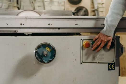
ISO 13850 and the legacy "five requirements" list converge on the same actuator rules: positive operation (mechanical, not just electrical, latching), always available and active, no defeat possible by software or remote signal, the actuator must be a mushroom or palm-cap in red on a yellow background, and the reset must be a deliberate manual action that cannot happen by accident [S3].
Geometric choices matter because ISO 13850 requires the actuator to be "easily accessible" and operable without hazard to the operator; in practice that means a 40 mm to 60 mm mushroom head for a hand-palm strike, a key-reset or twist-reset to release, and a yellow background with the red operator in front [S1][S8]. Where the operator cannot reach a fixed button (long conveyors, large robotic work envelopes, perimeter-guarded cells), a pull-cord E-stop with a red mushroom grab and a positively-opening limit-switch chain is the equivalent compliant solution, again on a Category 0 or Category 1 stop path [S5]. For flush-panel machine mounting, a 22.5 mm or 30.5 mm hole pattern with a twist-to-release or pull-to-release head keeps the operator profile below the guarding envelope and reduces snag risk.
Contact Blocks, Wiring, and Fail-Safe Architecture
The most common spec mistake is treating the contact block as a generic switch: a compliant E-stop block must be force-guided (positively driven) so that a welded NO contact cannot present a false closed state to the safety relay, and it must show a mechanical trip indicator independent of the electrical contacts [S1][S3].
Wire the block in dual-channel form: one normally closed channel to the safety relay (or safety PLC) input, with the second channel either another NC contact in series for cross-monitoring, or a NO contact used as a fault-monitoring loop. Powering the E-stop from the same protected supply as the safety relay, and using a self-monitored safety relay with EDM (external device monitoring) back to the contactors, is the canonical implementation for PL d / SIL 2 [S1]. For Category 0 hard stops, the contactors themselves should be mechanically linked and force-guided so that a single welded contactor cannot re-energise the load, and any bypass for maintenance must be a key-switch interlock, not a software flag.
Placement, Visibility, and the "One Press" Rule
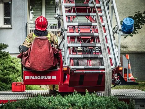
NFPA 79 and IEC 60204-1 both require E-stops at every operator control station and at any other location where an emergency stop could be needed, which in practice means one per work cell, one at every conveyor tail and head pulley, and one inside any guarded envelope large enough for a person to enter [S7][S8].
Mounting height is typically 0.6 m to 1.7 m above the floor for hand actuators, with the yellow surround visible against the machinery background and the actuator unobstructed by guarding or cabling. For conveyor lines longer than the operator's reach, E-stops must be spaced so that any point on the conveyor is within arm's length of a device, often interpreted as roughly 10 m to 20 m spacing depending on the application. Pull-cord systems with red grab handles running the full length of the conveyor are the common compliant answer for long runs, and they must latch positively and break the safety circuit when pulled in either direction [S1][S5]. Indoor E-stops as a category are usually rated to IP65 minimum, with IP67 or IP69K required for food-and-beverage washdown and outdoor mobile equipment.
What E-Stops Cannot Do, and What to Pair Them With
ISO 13850 and the EU Machinery Directive both state that the E-stop is a complementary protective measure, not a substitute for safeguarding: it is not a guard interlock, it is not a risk-reduction measure, and it does not replace lockout/tagout for servicing [S5].
That has three spec consequences. First, the E-stop must never be the primary reason a hazard is considered "acceptable" in the risk assessment; guards, light curtains, two-hand controls, and safety-rated mat edges have to stand on their own [S5]. Second, the E-stop is not an operational on/off switch, so a plant that needs a frequent local stop should add a non-emergency stop pushbutton wired to the normal stop circuit, not abuse the E-stop and erode its "never touch except in emergency" status. Third, the E-stop can be intentionally selective: a robot cell might have an E-stop that only drops the robot servo and not the vacuum pump, when removing all power would drop a suspended load, and the rationale must be documented in the Information for Use [S5]. When integrating E-stops into broader emergency rescue and evacuation logic, treat them as the trigger for machine stop, not for facility-wide power-down, which is the job of an Emergency Off (EMO) circuit on a separate, often red-black, mushroom per NFPA 79.
Selection Checklist and What NOT to Specify
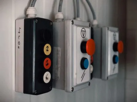
A defensible 2026 E-stop specification, in the order it should be filled out: risk assessment with S/F/P scoring, chosen stop category (0 or 1) with documented justification, target PL or SIL, contact-block topology (1NC/1NO dual channel minimum for PL c, redundant NC for PL d/e), actuator type (mushroom, key-reset, pull-cord), housing IP rating, placement map against the machine envelope, and reset logic (manual reset at the device, not remote) [S1][S3][S4].
Common spec failures to avoid: a single-channel contact block on a Category 3 risk (no diagnostic coverage), a black or grey button body instead of red-on-yellow, an illuminated or auto-reset head, software-driven reset, an E-stop used as a routine stop, and a pressure transmitter or flow meter alarm mapped onto the E-stop circuit just because the wires are convenient. The device must remain passively safe through loss of control power, so any spec that relies on a controller being online to keep the E-stop functional is out of compliance with ISO 13849-1 fault exclusions.
For a 2026 build, the realistic shortlist logic is: a 22.5 mm or 30.5 mm red mushroom, 1NC + 1NO force-guided contact block, IP65/IP67 housing, PL d / SIL 2 safety relay with EDM, for most discrete-machine cells; swap to a pull-cord with latching grab handle and dual limit switches on long conveyors; and step up to a Category 4 / PL e safety controller with redundant contactors on high-hazard robot or press lines. Audit trail signal: check the supplier's ISO 13849-1 PXCM ratings and the safety relay's PFHd figure against the target SIL on the next design review.
This topic is covered further in Laser Marker Sizing and Selection: Part-First Spec Map for 2026.