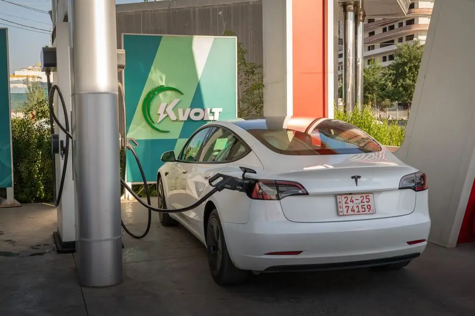
An EV charger bills down to five functional sub-assemblies: power supply, power module, control board, charging cable/connector pair, and enclosure, with a DC fast charger adding switchgear, a utility-side 480 VAC transformer, and typically a BESS stage [S1][S3].
Power range dictates the BOM weight: Level 1 AC units sit near 120 VAC and 2.4 kW, Level 2 AC units push 240 VAC and 19 kW, and Level 3 DC fast units span 480 VDC output and up to 350 kW per dispenser, with cabling alone shifting from copper-only to copper or aluminum conductors rated for sustained high current [S2][S4].
Charger Levels and Where Each Component Shows Up
Level 1 and Level 2 EV chargers use an AC power supply that takes grid AC and conditions it to the voltage and current the onboard charger accepts, while Level 3 DC fast chargers use a DC power supply that converts high-voltage grid AC to a regulated DC bus before the EV inlet [S2]. The five components named across manufacturer and OEM write-ups are consistent: power supply, charging cable, connector, control board, and user interface [S4].
Level 1 caps near 120 VAC and 2.4 kW; Level 2 sits at 240 VAC and up to 19 kW; Level 3 DC fast chargers cover up to 480 VDC and 350 kW output, and can refill a battery in roughly 30 minutes under commercial duty [S2]. The BOM scales with that power level: contactors, busbars, and cooling hardware dominate the DC fast bill, while the Level 1 BOM is essentially a small PCB, a relay, an enclosure, and a captive cable.
Power Module: IGBT vs MOSFET, PFC, and DC/DC
The power module is the bill-defining sub-assembly in any DC-capable charger, integrating IGBT or MOSFET switching devices with a PFC stage and a DC/DC conversion stage, plus busbars, cooling structures, and high-voltage interconnects [S3]. The choice of IGBT versus MOSFET is set by the required power level, with IGBTs typically carrying the higher kilovolt-ampere stages and MOSFETs serving mid-power stages.
Thermal management is not optional at 50-350 kW: Zeconex describes optimizing thermal conduction paths, current transmission efficiency, and electrical safety clearances during power module integration, then running power-on and load tests to validate stable power output before full-system integration [S3]. For perspective on how the same power-electronics discipline plays out in adjacent energy hardware, the BESS supply chain walkthrough at BESS supply chain stages shows identical IGBT, busbar, and thermal-stack decisions at pack and PCS level.
Control Board, Protection, and Communication
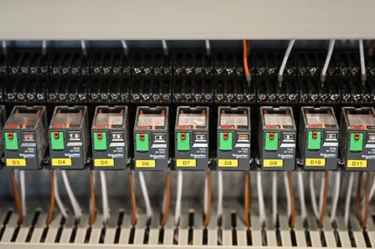
Every charger BOM includes a control board built around an MCU that runs charging logic, with relays and contactors handling inrush and fault isolation, plus capacitors, inductors, sensors, and signal connectors matched to the electrical design [S3]. Communication modules are typically 4G or Ethernet, with OCPP integrated so the unit can register with a backend charging management system [S3].
Protection is implemented at multiple layers: the control board handles low-voltage interlocks and ground-fault detection, while upstream switchgear provides overcurrent and disconnect functions. A DC fast site receives 480 VAC utility power at a power disconnect panel with breaker fault protection, then routes through a CT cabinet and utility meter before reaching the distribution panel and step-down transformer that supplies 120/240 VAC site loads [S1]. Cable current and voltage ratings are set by the connector standard and the charger's nameplate output, not by the site AC voltage.
Charging Cable and Connector Standards
Charging connectors are the most region-sensitive line item in the BOM, with Type 1, Type 2 (Mennekes), CCS, CHAdeMO, GB/T, and the Bharat AC-001 and DC-001 variants each defining their own cable, pin, and current ratings [S3][S4]. Cable conductors are typically copper or aluminum, sized to support the weight of the EV-side coupler and the continuous current the connector carries [S2].
Connector selection sets both the cable BOM and the certification cost. Type 1 is a 5-pin connector common in North America and Japan, rated up to 16 A for slow and medium-speed charging; Type 2 (IEC 62196) is the EU standard, 7-pin, supporting up to 43 kW; CCS combines Type 2 AC pins with two DC pins for up to 350 kW; CHAdeMO originated in Japan, launched a 62.5 kW connector in 2010, and is now specified up to 400 kW [S4]. For raw-material risk on the copper and aluminum in those cables, the EV charger raw material sourcing map breaks down conductor, polymer, and contact-alloy exposure by region.
Enclosure, Thermal Hardware, and Site Infrastructure
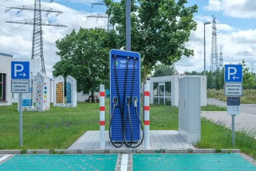
Enclosure design follows the installation mode (wall-mounted versus pedestal) and must deliver the IP rating, impact resistance, and UV stability the install environment demands; cooling hardware, fans or liquid cold plates, integrates directly with the power module rather than living as a separate BOM line [S3]. DC fast sites add a second hardware layer outside the dispenser: the utility transformer steps transmission voltage down to 480 VAC, which is the standard industrial and commercial input for multi-charger sites [S1].
Three DC fast topologies sit on top of that infrastructure BOM. All-in-one units put the charger, power electronics, and communications in a single enclosure, suited to small-scale sites. Power-cabinet designs split those functions into modular cabinets for medium and large-scale sites. Integrated BESS configurations pair the DC fast charger with on-site battery storage to shave peak grid demand at sites with weak or unreliable grid infrastructure [S1]. The BESS raw material sourcing brief covers what changes in the cell, BMS, and PCS BOM when a charger ships with an integrated BESS stage.
Comparison: AC Level 2 vs DC Fast BOM Lines
Four BOM criteria separate Level 2 AC from DC fast. Power range: Level 2 caps at 240 VAC, 19 kW, while DC fast spans 480 VDC output up to 350 kW [S2]. Switching devices: Level 2 is largely relay and small-signal MOSFET, DC fast is IGBT-dominated with PFC plus DC/DC stages [S3]. Cable and connector: Level 2 uses Type 1 or Type 2 AC couplers up to 43 kW; DC fast uses CCS, CHAdeMO, or GB/T with sustained current ratings and liquid-cooled options at the top end [S4]. Site infrastructure: Level 2 typically lands on an existing 240 VAC branch circuit, while DC fast needs switchgear, a CT cabinet, a utility meter, distribution panels, a step-down transformer for 120/240 VAC site loads, and often a dedicated 480 VAC utility transformer owned and maintained by the utility [S1].
Selection Signals Worth Tracking
Two verifiable signals will reshape the EV charger BOM through 2026. Connector mix is shifting toward CCS and GB/T as Type 1 fades from new EU and APAC designs, which will change cable and contact-alloy sourcing volumes [S4]. Integrated BESS configurations are appearing on weak-grid sites to shave peak demand, which adds cells, a BMS, and a PCS to the BOM on top of the standard DC fast stack [S1].
For the relevant spec sheets and selection criteria, see shaft key, construction machinery and equipment, and lamps and light fittings.