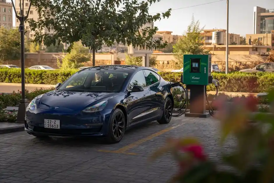
800 V EV architectures are now driving single-stage AC/DC charger designs, with a three-level neutral-point clamped (T-NPC) converter handling grid-side power-factor correction and real-time battery charging in one power pass, validated on a unit and a real battery in a 2025 study [S1].
The instrumentation scope covers AC-side metering, DC link voltage and current sensing, isolation monitoring, thermal sensing on the power module, and PLC/RTU-level control of the dispenser, energy storage, and any co-located PV or battery buffer [S2][S5].
Charging Levels and Power-Converter Topology Options
EV supply equipment is split into AC Level 1, AC Level 2, and DC fast charging, with DC fast chargers typically rated from 50 kW to 350 kW+ and operating at 400 V or 800 V battery packs [S5]. Two-stage chargers use a grid-side PFC rectifier feeding an isolated DC/DC stage; single-stage chargers, as in the 2025 800 V study, fold both functions into one T-NPC converter fed through a low-frequency transformer and LCL filter, with reported validation including V2X reverse power flow [S1]. Across converter families, the comparison that matters at procurement is efficiency, bidirectional capability, and 800 V native support:
Two-stage PFC + isolated DC/DC: established, modular, easier to scale, but extra conversion stage lowers peak efficiency.
Single-stage T-NPC: fewer parts, native 800 V support, built-in V2X, but control loop tuning is tighter and transformer design is application-specific [S1].
Phase-shift full-bridge DC/DC: common in 400 V and 800 V DC fast stacks, simple isolation, but limited bidirectional reuse without topology changes [S1].
Process Variables and Sensor Selection
Inside the dispenser, the process variables that drive closed-loop control are AC line voltage and current (for PFC and dispatch), DC link voltage (typically 400 V or 800 V class), DC output current, isolation resistance to ground, and module inlet/outlet temperatures on the liquid-cooled cold plate [S2][S5]. Temperature is almost universally read with 10 kΩ NTC thermistors or RTDs bonded to the IGBT/SiC baseplate, with trips set well below the power-module junction rating [S2].
For grid-side billing and dispatch, the AC meter class is typically 0.5S or better, with a Modbus TCP or DNP3 link to the site energy management controller, which is the same controller that talks to the upstream SCADA over IEC 61850 or a utility API [S2]. OCPP 1.6/2.0.1 is the back-office protocol between the charger and the network operator, distinct from the EV-to-charger signalling on the pilot line.
Standards Governing the Control Loop
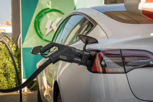
IEC 61851-1 defines the four charging modes (1 through 4), the pilot-function control line, and the basic safety envelope; SAE J1772 and the GB/T 27930 family mirror the same architecture in the North American and Chinese markets respectively [S4]. ISO 15118 governs the high-level digital communication between the EV and the charger, including plug-and-charge authentication, charging schedule negotiation, and bidirectional power transfer profiles used in V2X [S1]. UL 2231 covers personnel protection against electric shock on both AC and DC outputs in North America, while IEC 61851-23 specifies the DC charging control and monitoring requirements at the system level [S4].
For grid integration, IEEE 1547 and the local interconnection code set the ride-through and reactive-power behaviour; IEEE 2030.5 or IEC 61850-90-5 are common for DER-to-utility messaging when the charger is treated as a dispatchable resource [S2]. None of these are interchangeable: OCPP is back-office, ISO 15118 is EV-to-charger, IEC 61850 is substation/DER comms.
Bidirectional Operation and Energy-Storage Coupling
V2X, including V2G, V2H, and V2L, is implemented by reversing the active power flow through the same converter that performs forward charging, with the T-NPC study reporting both grid-to-vehicle and vehicle-to-grid modes on the same hardware [S1]. Where the site co-locates a stationary battery or PV, the energy management controller dispatches between the AC source, the buffer storage, and the EV, with the converter acting as the controlled current source on the DC bus; DC-bus architecture is preferred over AC distribution because of higher conversion efficiency, simpler renewable interfacing, and easier storage integration [S5].
For sites where multiple dispensers share a single medium-voltage transformer, a site-level controller arbitrates power to stay inside the service capacity, throttling individual dispensers rather than tripping upstream protection; this is where the process-control discipline inside a charging cabinet starts to resemble a small substation.
Who This Architecture Is For, and Where It Falls Short

Single-stage 800 V chargers with V2X make sense for new-build highway-corridor sites targeting 800 V BEVs, fleet depots with on-site renewables, and locations where a stationary buffer is already present, because the bidirectional converter doubles as a grid-support asset [S1][S5]. Two-stage PFC + DC/DC remains the lower-risk choice for mixed-fleet 400 V/800 V sites and for retrofit on existing AC distribution, since the modular DC/DC stage absorbs the 400 V/800 V mismatch without redesigning the grid-side rectifier [S1].
Where the architecture falls short: legacy AC Level 1/2 dispensers that depend on the vehicle's onboard charger, sites without an EMS-capable back office (OCPP 1.6 minimum), and any installation where the utility will not permit reverse power flow, because then half of the T-NPC's capability is stranded [S1][S2].
Limitations, Failure Modes, and Sourcing Reality
Process-control reliability in fast charging is dominated by three failure modes: thermal runaway in the SiC/IGBT module at sustained high power, isolation degradation under DC bias on the HVDC bus, and pilot-line communication loss that defaults the dispenser to a safe-state but locks the connector [S2][S4]. A 2025 review on EV charging station operation and dispatch confirms that meticulous real-time optimization of charging schedules and power dispatch is required to avoid grid bottlenecks and infrastructure over-build, particularly at depot scale where multiple high-power sessions coincide [S3].
On sourcing, the procurement pathway typically separates the power module (converter + filter + transformer), the dispenser (cable, connector, HMI, payment terminal), the site controller, and the back-office service, with NEVI and similar public programmes in the US locking in Buy America or local-content rules that effectively split the supplier list by region [S2]. Lead time on medium-voltage transformers and high-power SiC stacks remains the binding constraint on new DC fast sites.
Trackable signals worth watching: the rollout of MCS (Megawatt Charging System) for heavy-duty trucks, which uses the same ISO 15118 protocol family but at 1.2 MW+ per dispenser, and the slow migration of OCPP 1.6 deployments to OCPP 2.0.1, which enables the smart-charging features that the EV charging station process control stack above assumes.
The underlying component specifications are covered under total station, and weather station.
Background reading: SPC Flooring Selection for High-Rise Buildings: Specs, Acoustic Codes, and Wear Layer.