
Electric-vehicle manufacturing in 2026 is structured around four hard-spec nodes: 1200 V silicon-carbide (SiC) power devices, LFP and NMC prismatic/pouch cells, high-voltage battery-management system (BMS) contactors, and DC-fast-charging electric actuators for thermal-management valves. China's "dual carbon" framework continues to anchor the upstream capex cycle that began in 2021, with CLP's David Simmonds stating the policy gives "confidence and a clear direction for businesses" while "accelerat[ing] the green transition" [S3].
The downstream side now extends well beyond passenger cars into commercial trucks, two-/three-wheelers in South-East Asia, and stationary battery storage reusing retired traction packs. Indonesia's Joko Widodo has explicitly courted German capital for EV industry build-out since June 2022, framing the upstream/downstream chain as a multilateral investment target rather than a single-OEM problem [S2].
Upstream Layer 1: SiC Wafers, Epitaxy and 1200 V MOSFETs
The binding upstream bottleneck in 2026 is still 150 mm/200 mm SiC epitaxy and the ramp of 1200 V SiC MOSFETs for 800 V traction inverters. Domestic Chinese epitaxy lines built on the Innoscience (Zhuhai) Technology model — the first complete mass-production line of epitaxy and chips in the country, established years before the 2026 cycle — remain the reference template for greenfield SiC fabs targeting automotive-grade electric ball valve and inverter duty [S1].
Volume SiC MOSFETs in 2026 are commonly specced at 1200 V breakdown, 15-40 mΩ R<sub>DS(on)</sub> in TO-247-4 or top-side cooled packages, with AEC-Q101 automotive qualification and PPAP documentation. Substrate supply remains concentrated among a handful of vertically integrated lines; epitaxial-layer thickness is typically 6-15 µm with doping in the 1×10<sup>15</sup> cm<sup>-3</sup> range, and the upstream bottleneck is the ability to grow thicker, lower-defect epitaxy for higher-voltage (1700 V and above) rail and grid-tie inverters.
Upstream Layer 2: LFP vs NMC Cell Chemistry and Pack Formats
Cell chemistry in 2026 splits along cost-per-kWh vs energy-density axes. LFP prismatic cells dominate Chinese mass-market BEVs and stationary storage at typical 160-200 Wh/kg pack level, while NMC 811 or NCA cylindrical (4680) and large-format prismatic cells remain the choice for performance passenger cars and most European platforms. C-rate requirements diverge: 2-3 C continuous discharge for traction, 0.5-1 C for energy-storage second-life packs. [S1]
Form factors in active use are 4680 cylindrical (≈ 46 mm × 80 mm), 2170 (21 mm × 70 mm), VDA/PHEV prismatic, and BYD-style blade cells. Module-to-pack (CTP) and cell-to-pack (CTP) configurations now exceed 70% volumetric utilisation in many Chinese BEV programs, eliminating traditional module housings and shifting upstream demand from steel/aluminium module hardware to structural adhesive and foam suppliers.
Midstream: BMS, High-Voltage Contactors and Pre-charge Logic
Battery-management systems in 2026 typically spec 12-18 cell-monitoring ICs per master, with ±2 mV voltage accuracy, isolated CAN-FD or 100BASE-T1 communication, and ISO 26262 ASIL-C/D functional-safety targets on the ASIL-D decomposition. High-voltage contactors are specced at 400 V/800 V ratings, 200-400 A continuous, with mechanical life beyond 100,000 cycles and pre-charge contactors sized for 10-50 Ω pre-charge resistance to limit inrush below 300 V/µs. [S2]
Functional-safety decomposition for ISO 26262 demands redundant measurement paths for cell voltage, pack current (typically via closed-loop Hall or shunt at ±0.5% accuracy) and isolation monitoring. BMS master units increasingly embed 32-bit lockstep cores (Arm Cortex-R52 or equivalent) and ISO/SAE 21434 cybersecurity conformance, since UN R155/R156 have made software-update governance and a certified cybersecurity management system a homologation prerequisite across major markets.
Downstream Layer 1: 800 V Architecture, DC Fast Charging and Thermal Management
The thermal-management side uses a single or dual-loop coolant circuit with industrial valve assemblies (typically electronically actuated, 1/2" to 1-1/4" O/D lines) to feed the inverter, the on-board charger (OBC), and the battery cold plate. [S3]
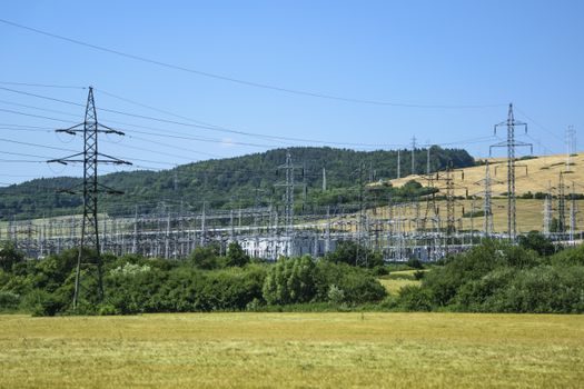
DC fast-charging stations in 2026 ship at 150 kW, 350 kW and increasingly 600 kW liquid-cooled cabinets. The downstream power-electronics chain requires the same SiC MOSFETs used onboard the vehicle, plus PFC + LLC or three-level NPC topologies. Grid-side, GBT (gate bipolar transistor) or SiC stacks feed 480-800 V DC buses, with bidirectional capability in many CCS2/GB/T stations to support V2G (vehicle-to-grid) pilot projects, especially in European and Chinese hubs.
Downstream Layer 2: Assembly Tooling, Torque and Traceability

Final-assembly tooling determines what actually ships. Battery-pack torque specs for M6-M12 cell-to-busbar and pack-to-chassis bolts are typically 8-25 Nm on cell connections and 80-150 Nm on chassis bolts, with a ±5% torque-accuracy requirement. Multi-spindle nutrunners with angle-of-turn monitoring (e.g. 30-720° turn after torque snug) are now standard on Chinese, European and Korean lines, and torque data are logged per-vehicle for end-of-line traceability. [S1]
For a 2026 buying engineer, the up/down chain reads as: (1) SiC epitaxy + MOSFET vendor (capex, lead-time 18-36 months), (2) cell vendor (chemistry, form-factor, C-rate), (3) BMS master + contactor + current-shunt vendor (functional-safety and ISO/SAE 21434 evidence), (4) HVAC/thermal flow meter + electrically actuated valve chain, (5) DCFC cabinet supplier and grid interconnect, and (6) assembly torque tooling with per-vehicle data logging. A useful selection lens for the next plant build is given in the planetary reducer sizing 2026 guide, which covers the gearhead and torque-transmission thinking that mirrors the same spec-first logic used on pack-assembly spindles. For a sister heavy-industry reading of upstream/downstream chain analysis, the nuclear power 2026 spec snapshot lays out comparable upstream/downstream mapping for nuclear, useful as a benchmark.
Constraints, Failure Modes and 2026 Watchpoints
The dominant failure modes on a 2026 EV program are SiC gate-oxide degradation under short-circuit, BMS contactor welding at end-of-life, thermal-runaway propagation between cells in CTP packs, and torque-loosening on chassis bolts (typically controlled with threadlocker or wedge-lock washers). Mitigation lives upstream: gate-drive layout, contactor derating, cell-to-cell spacing ≥ 3 mm, and bolted-joint preload control via angle-of-turn strategies. [S2]
Trackable signals for the rest of 2026: UNECE R155/R156 enforcement checkpoints, EU Battery Regulation 2023/1542 passport compliance, and the next wave of 800 V/350 kW DCFC cabinet rollouts in Germany, Indonesia and the Gulf. Buyers should watch ISO/SAE 21434 audit reports from certified suppliers, since cybersecurity evidence is now a homologation gate and a working pressure-transmitter vendor file is a useful proxy for the kind of spec discipline needed across the chain — see the pressure transmitter reference for the level of documentation rigor that downstream EV hydraulic and thermal loops will increasingly require.