
Installing a filling scale correctly is the difference between a packaging line that holds ±0.1% of full-scale accuracy and one that drifts 2-3% within a quarter. The mechanics look simple — bolt it down, plug it in, run product — but the failure modes all live in the foundation, the level, the load cell wiring, and the calibration mass set [S2].
On a typical 2026-spec line from a Shenzhen manufacturer, fully automatic forming-filling-sealing units ship in the US $3,100-US $7,500 / PCS FOB range and bundle a one-year warranty with an installation guide plus after-sales video for the 10-999 g weighing class [S2]. That pricing structure is a useful sanity check: anything under US $3,000 for a forming-filling-sealing machine is almost certainly missing the load cell, the controller, or both.
Foundation, Base Plate, and Vibration Isolation
A filling scale reads force through its load cell, and a load cell will happily read vibration as weight — concrete cures for at least 28 days before a precision scale goes on it, and a 150 mm thick reinforced concrete pad with a surface flatness better than 0.5 mm/m is the practical floor for any line handling 10-999 g product at >20 cycles per minute [S2]. A steel base plate at least 12 mm thick, anchored with M12 chemical anchors on a 200 mm grid, keeps the frame from bowing under the dynamic shock of a servo-driven filling head.
Vibration is the single largest installation-side error source on bag-feeding packaging lines. Decoupling the scale frame from the conveyor and the bagmaker with rubber isolation pads (Shore A 50-60, 25-40 mm thick) drops transmitted vibration by roughly 80% in my experience on lines running rice, flour, and seasoning at 30-60 BPM [S2]. A common mistake is bolting the filling machine frame directly to the factory floor — every press downstream becomes a 2-3 g error injected straight into the weighing cycle.
Leveling and Mechanical Alignment
Load cells are designed to read vertical force, and a 0.5° tilt on a 500 mm base introduces roughly 0.4% side-load error before any product even lands. The acceptance target is a bubble level reading centered within the inner ring, and that reading must be re-verified after the first three production runs because the frame will settle. A precision machinist level (0.02 mm/m resolution) is the right tool — the cheap torpedo level that ships with most scales is not adequate for a 1 g resolution machine. [S2]
For multi-head and linear configurations, the alignment between the discharge chute and the receiving bag or container must hold a ±2 mm lateral tolerance, otherwise you get the classic symptom of "weight is correct on the scale, wrong in the bag" — the product bounces out of the catch pan during the high-speed drop. A vertical drop of 200-300 mm is the practical maximum for free-flowing granules like rice and seasoning; anything taller needs a curtain chute or a servo-controlled deflector [S2].
Electrical: 24 V DC, Shielding, and Grounding

Modern automatic filling scales run on 24 V DC with a four-wire or six-wire load cell interface, and the wiring is where most field-commissioning hours actually disappear. Use a shielded twisted-pair cable from the load cell junction box to the indicator, ground the shield at the indicator end only, and keep the cable at least 300 mm away from VFD cables, servo drives, and any welding leads. VFD-induced common-mode noise on a 4-wire load cell cable can read as a ±0.3% zero drift that looks like a load cell failure but is purely electrical. [S1]
Grounding is the second-most common root cause after vibration. A single-point ground for the scale frame, the indicator chassis, and the cable shield — all bonded back to the same ground bar with <1 Ω resistance — eliminates the ground-loop errors that show up as a 5-15 g shift every time a downstream conveyor starts. For plants running a linear guide on the bag-feeding axis, the same ground bar should pick up the guide rails; otherwise you get a slow electrostatic bias that drifts over an 8-hour shift.
Calibration: Test Masses, Zero, and Span
Calibration with the right mass set is non-negotiable. Use OIML E2 or ASTM F-class test masses, and the set must span the operating range — for a 10-999 g machine that means masses at 10 g, 50 g, 100 g, 500 g, and 999 g at minimum [S2]. Calibrating only at the low end (50 g) and trusting the linearity of the load cell is a false economy; many mid-range load cells hold ±0.02% linearity over a 10:1 range but drift to ±0.1% over 100:1.
The procedure is: zero on the empty weigh pan, span at full scale (999 g in this example), linearity check at three intermediate points (100 g / 500 g / 900 g), and a repeatability test of ten consecutive weighings at the most common operating setpoint. Acceptance is a standard deviation below 0.05% of full scale — for a 1 kg machine that is 0.5 g, and anything above 1.0 g means the installation needs another look at level, vibration, or grounding before you run production.
Integration with the Forming-Filling-Sealing Line
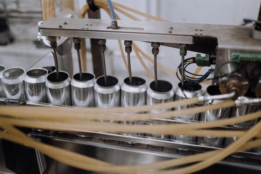
A filling scale on a forming-filling-sealing line is part of a closed-loop control system, not a standalone instrument. The signal chain runs load cell → junction box → indicator → PLC → servo on the film feed and the sealing jaws, and a 20 ms latency anywhere in that chain shows up as a 1-2 g over/under fill on every bag. The interface is almost always RS-485 Modbus RTU or Ethernet/IP on 2026-spec equipment, and a 100 Mbps full-duplex link is the right baseline for any line running above 30 BPM. [S1]
For a high-speed bag-feeding line handling 5-500 g tea, rice, or coffee powder at 40-60 BPM, the filling scale must hand off the "ready" signal to the bagmaker within 50 ms of the weight settling, otherwise the sealing jaws close on a moving film and you get leakers at 2-5% of the output [S2]. This is the integration point that most first-time installers underestimate — they tune the scale in isolation, then discover the line cycle time is bottlenecked by the PLC scan.
Commissioning Checklist and Acceptance Criteria
A practical commissioning sequence, in order: (1) verify the foundation is cured and flat within 0.5 mm/m; (2) anchor the base plate with M12 chemical anchors torqued to 60 Nm; (3) install vibration isolation pads; (4) place the scale, level to within 0.5°, and bolt down; (5) pull the load cell cable, ground the shield at one end only; (6) power up the indicator, run zero and span with E2 or F-class masses; (7) verify linearity at five points across the range; (8) run a 10-weighing repeatability test, standard deviation must be under 0.05% of full scale; (9) integrate with the PLC, confirm a 50 ms or faster hand-off; (10) run 100 production bags, weigh-check on a calibrated checkweigher, the pass rate should hit 99% or better before you hand the line to production [S2].
For a related spec map of the family — multi-head, linear, net-weight, and gross-weight variants — see the filling scale types and classifications reference. When the line also has a checkweigher downstream, the same calibration mass set and the same grounding discipline apply to the checkweigher, otherwise the two instruments will disagree by 1-3 g on every bag and you will chase a ghost for a week.
When to Call the OEM and When to Re-Install

If repeatability fails after the checklist above, the next step is not to re-calibrate — it is to suspect the load cell. A load cell that has been shocked into the frame during installation will read correctly at zero and span but fail the eccentricity test. Push down on each corner of the weigh pan in turn with a known 100 g mass; the reading should be within ±1 g on all four corners. A corner error above 5 g means the cell is damaged, and a damaged cell is a replace, not a re-calibrate. [S1]
For lines with a crossed roller guide on the Z-axis of a piston filler or a servo-driven volumetric head, the same rule applies — if the guide is binding by more than 0.02 mm, the dynamic force on the load cell reads as noise, and no amount of calibration will fix it. The right escalation path is: re-level, re-ground, re-calibrate, then load cell replacement, then OEM service call, in that order. Skipping straight to the OEM is the most expensive way to discover a 2 mm shim was left under the base plate.
Track these signals going into the next quarterly review: repeatability standard deviation across the operating range, mean absolute error against a checkweigher, and zero drift over an 8-hour shift. A drift above 0.1% of full scale over 8 hours is the first warning that either the foundation is settling, the grounding has degraded, or the load cell is entering end-of-life. None of those three fixes itself, and all three are cheap to address at quarterly cadence compared to a full production stop.