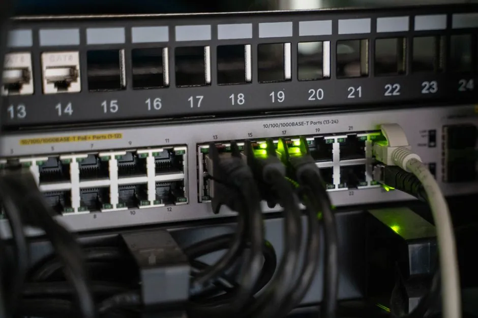
About 95% of fixed gas detection systems installed in industrial plants still communicate on the field segment via 4-20 mA analog loops, even as digital options (Modbus/RTU, Foundation Fieldbus, Industrial Ethernet) gain ground in new builds [S5].
2-wire loop-powered 4-20 mA transmitters carry both signal and supply on the same pair, while digital bus options such as RS-485 Modbus/RTU use a twisted pair shared across many nodes [S3][S5]. For a process engineer selecting a fixed gas detector head, the wire decision drives cable count, conduit sizing, and the choice of input card on the controller.
How a 4-20 mA Loop Behaves on a Gas Detection Riser
A 4-20 mA current loop represents 0% measurement as 4 mA and 100% as 20 mA, with the live-zero offset (4 mA ≠ 0 mA) used to distinguish a powered healthy sensor from a broken wire [S4][S6]. The signal is current, not voltage, so loop accuracy is largely immune to lead resistance over hundreds of metres; a sensor mounted 500 m from the controller reads the same as one mounted 5 m away as long as the supply voltage covers the loop budget [S3][S4].
Loop-powered 2-wire devices draw all operating current from the same pair, simplifying explosion-proof gland counts but capping sensor power at roughly 3.5 mA on a 24 VDC supply after the 4 mA live-zero baseline is taken [S1][S3]. 4-wire variants separate power and signal on independent pairs, freeing current budget for heated sensors, IR optics, or onboard displays, at the cost of an extra cable run per point [S1][S3].
On a digital multimimeter bench check, a healthy 4-20 mA gas transmitter should sit between 3.8 and 4.2 mA in clean air, climb to 20.0 mA at full scale, and drop to 0 mA or read negative on a broken wire, a fault signature that PLCs and DCSs treat as a hardware failure rather than a gas reading [S6].
How Digital Bus Wiring Carries the Same Data
RS-485 Modbus/RTU is the most common digital fieldbus on fixed gas detectors: a single shielded twisted pair carries half-duplex differential signalling at 9600 to 19200 baud typically, with up to 32 nodes per segment and a maximum stub-free run near 1200 m at the lower baud rates [S5]. Each detector gets a unique address (1-247), and concentration, range, calibration date, and fault flags are read as holding registers instead of being inferred from current level [S2][S5].
Industrial Ethernet variants (PROFINET, EtherNet/IP, EtherCAT, plus the APL profile on 2-wire) push bandwidth above 10 Mbit/s, far above gas detection's T90 response, which typically lands between 15 s and 60 s for electrochemical and catalytic-bead heads and a few seconds for IR [S5]. The relevant advantage is therefore not speed; it is multi-drop cable economics and remote access to instrument health, not raw throughput.
Digital does not mean "no analog": protocols such as HART (Highway Addressable Remote Transducer) superimpose a 1200 bps FSK signal on top of a standard 4-20 mA loop, so a HART-enabled fixed gas detector still occupies an analog input but exposes range, tag, and diagnostic data over the same pair [S5].
Selection Criteria: Wire Type by Project Profile
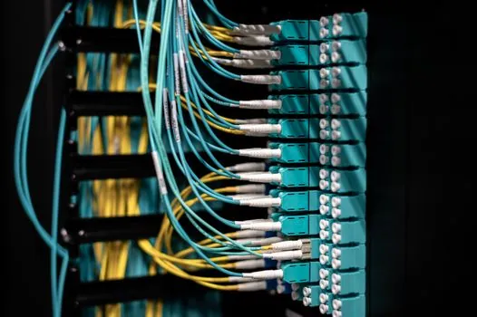
Pick 4-20 mA when the point count is low (under ~30 detectors), cable runs exceed 300 m, the controller has plenty of spare analog inputs, and the BMS cannot terminate RS-485 cleanly. Pick Modbus/RTU or HART when detector counts exceed ~30, you need per-detector calibration logs, or your digital panel meter fleet already supports multidrop polling [S2][S5][S7].
Concrete trade-off table, drawn from the same sources:
<strong>4-20 mA analog loop</strong>: 2 or 4 wires per detector (independent home run), immune to lead resistance, live-zero fault detection, simple panel-meter readout, easy loop calibration with a loop calibrator; drawbacks: one input per point on the controller, no remote configuration, no per-detector diagnostics beyond the current level [S1][S3][S4].
<strong>Modbus/RTU on RS-485</strong>: 1 twisted pair for up to 32 detectors, full register map (gas, range, cal date, fault), polling latency 100-500 ms per node; drawbacks: addressing and termination discipline required, single cable break can take down a segment, terminators needed at both ends, 1200 m max at 9600 baud [S2][S5].
<strong>HART on a 4-20 mA pair</strong>: keeps the analog input slot and the loop-powered wiring, adds tag/range/diagnostic data over the same pair; drawbacks: a HART-enabled controller or asset-management tool is needed to read anything beyond 4-20 mA, and a gas detection system integrator with HART experience is still uncommon on small BMS jobs [S5].
For the heavy-forklift corridors and loading bays where 4-20 mA already runs, the Fixed Gas Detector Coverage Radius: Sensor Spacing Rules per Location reference map is the next read after the wiring choice is locked in.
EMC, Cable Type, and Conduit Sizing Reality
4-20 mA is a current-mode signal, so electromagnetic pickup appears as a common-mode disturbance that the receiver rejects, in contrast to 0-10 V or 0-5 V voltage loops, which can drift several percent over the same run when routed next to VFD cables [S1][S3][S7].
Recommended cable for a new 4-20 mA gas detection riser is shielded twisted pair, typically 16 AWG (1.31 mm²) for long runs to keep voltage drop under 4 V at 20 mA, with the shield grounded at the controller end only to avoid ground loops [S1][S4]. RS-485 Modbus cable uses the same physical medium but requires a 120 Ω termination resistor at each end of the bus and a defined baud rate set identically on every node [S5].
Conduit fill math: a standard 3/4" EMT (21 mm ID) accepts about six 16 AWG shielded pairs; a typical analog gas riser with 12 detectors needs 12 home runs (24 conductors plus shields), which usually forces a 1-1/4" (41 mm) conduit or a second parallel run, while the same 12 detectors on a single RS-485 pair need only one conduit slot [S1][S5].
Limits, Failure Modes, and What Each Wiring Cannot Do
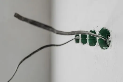
4-20 mA cannot tell you that the sensor is drifting in calibration, only that the present reading is x% of range; it cannot carry a tag, a serial number, or a last-calibrated date without a side channel such as HART [S2][S5]. A 4-wire analog loop is also vulnerable to a single break per point: cut the home run and that one detector goes dark while the others stay live.
Modbus/RTU cannot detect a wire break the way 4-20 mA can via its 0 mA fault level; a severed RS-485 pair typically returns a communication error on every node, leaving the controller to flag the whole segment as "unknown", and a missing termination shows up as rising error counts rather than an obvious fault [S2][S5]. Baud-rate mismatch between a new detector and an old controller is a common commissioning trap, and RS-485 repeaters become mandatory beyond 32 nodes or when the run exceeds the rated 1200 m at low baud [S5].
Industrial Ethernet solves the segment-length and node-count ceiling but introduces IT-layer concerns (managed switches, VLANs, cybersecurity patching) that a small analog gas panel does not have, and it requires the integrator to read the wiring duct layout against the new cable-bend-radius rules for CAT6A or APL two-wire segments [S2][S5].
Standards, Sourcing, and Engineering References
The 4-20 mA current-loop standard traces back to ISA SP50, originally published in 1966, and remains the default analog signalling layer in process control worldwide [S5]. Hazardous-area deployment of either wiring type is governed by the IEC 60079 series for explosive atmospheres, with ATEX 2014/34/EU and IECEx Schemes governing equipment certification in their respective regions; cabling practice for intrinsically safe loops falls under IEC 60079-14 [S1].
For larger plant builds, the practical sourcing path is to specify the controller input count (analog I/O vs RS-485 master) up front, then let the detector vendor offer a fixed gas detector variant in either 4-20 mA or Modbus/RTU from the same housing, a pattern already common across GfG, Critical Environment, and Prosense product lines [S2][S5][S7].
Trackable next signal: confirm whether the project controller (BMS, DCS, or PLC) supports multi-drop RS-485 polling natively or only via an add-on card, and pin down whether the existing cable tray has free capacity for either a parallel 4-20 mA home-run bundle or a single shielded RS-485 backbone before finalising the BOM [S1][S2][S5].