
A correctly specified relay module starts with three numbers: coil voltage, contact current/voltage, and channel count. Get those wrong and the board either never pulls in, or it welds shut on the first inductive spike.
The current market (catalog data reviewed 2026-08-31) spans 1-channel hobby boards at 5V DC up to 8-channel DIN-rail modules with 10A/250VAC contact sets and RS-485/Modbus RTU control [S1][S2][S3][S9]. Buyers who skip the rating math usually replace the module inside six months.
Coil Voltage and Trigger Logic: 5V, 12V, 24V, and the High/Low Question
Coil voltage is the single most-selected spec on a relay module datasheet, and the catalog mix in 2026 shows 5V DC, 12V DC, and 24V DC dominating the entry- and mid-tier [S2][S4][S8]. The Arduino-class reference module lists a 5V DC coil, 10A / 250VAC maximum AC load, and 10A / 30VDC maximum DC load with active-LOW trigger as the default [S2]. Industrial 24V DC modules with 36.9 mA nominal input current at UN=24V are common on Phoenix-style rails, with a permitted input voltage range of -20% to +10% [S4].
Trigger logic is the second decision: high-level trigger pulls the relay on when the input is logic high, while low-level trigger pulls on at logic low [S8]. Choosing the wrong level inverts every command you send, so verify against your controller (Arduino, ESP8266, Raspberry Pi, PLC) before ordering. Field note: optocoupler-isolated inputs are worth the small cost premium whenever the control side and the load side run from different supplies [S2].
Contact Rating: 10A/250VAC Is Not a Marketing Number
Contact rating tells you the absolute ceiling, and the figures buyers actually see on 2026 datasheets cluster around 10A at 250VAC (resistive) for general-purpose boards and 5A limiting continuous current for DIN-rail modules with AgCe contacts [S2][S4]. The 24V Phoenix-style relay module cites AC-15: 1A / 240V and DC-13: 2A / 24V utilization categories, which are the inductive-load ratings engineers should use when switching solenoids, contactors, or small motors rather than the higher resistive figure [S4]. Inrush on the same module is rated 15A resistive for 4 seconds, which matters for lamp, capacitor, and motor starting transients [S4].
Recommended minimum load (12V / 100 mA on the module above) is the floor below which silver contacts can oxidise and the relay fails to make the circuit reliably [S4]. Solid-state relay (SSR) modules remove that minimum-load problem and also eliminate the mechanical bounce, but they trade it for a higher on-state voltage drop and strict thermal derating above a few amps. Comparison summary for the most common contact options in this category:
Electromechanical (EMR), AgCe/AgSnO2 contacts, 10A/250VAC resistive, 1A/240VAC AC-15, optocoupler isolated, lowest cost, mechanical wear, 100,000-cycle class.
Solid-state (SSR), zero-cross or random-on triac/MOSFET, 2A–40A typical, 5mA–1A leakage when off, no minimum load, higher thermal loss per amp, longer life in high-cycle use.
Reed-relay modules, hermetic reed contacts, 0.5A–1A typical, fast switching, low coil power, fragile to inrush, limited to signal-level and low-power DC.
Channel Count, Protocol, and Wiring Topology
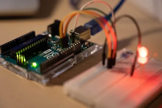
Channel count drives both cost and panel real estate, and the 2026 buyer guide lines up the duty cases cleanly: 1-channel for single-appliance control, 2-channel for light plus fan or motor forward/reverse, 4-channel for full-room automation, and 8-channel for multi-room or industrial panels drawing around 600 mA or more on a mandatory external 5V supply [S9]. Multi-channel DIN modules with four changeover contacts and 5A limiting continuous current are widely stocked for control-panel builders [S4][S7].
For protocol, three families dominate. Dry-contact / GPIO input boards take a single logic pin per channel and are the cheapest path for Arduino, ESP, and Raspberry Pi projects [S2][S8]. RS-485/Modbus RTU boards, typically DC 7V–24V powered, support multi-drop addressing of up to 32 or 256 nodes on a twisted pair and are the standard pick for building-automation and lighting-control cabinets [S1][S3][S7]. TTL/USART single-channel boards sit in between, useful when the host already exposes a serial port and you want framed commands instead of bit-banging [S1]. Comparing the three on a 2-axis decision: cost per channel is lowest for GPIO, longest cable runs and node count are best for RS-485/Modbus, and lowest firmware effort on a single-channel MCU is the TTL/USART path.
Protection Features That Decide Reliability
Flyback diodes across the coil and a snubber or varistor across the contacts are not optional on inductive DC loads, and 2026 catalog boards almost universally include at least the diode [S2][S5]. Optocoupler isolation between the MCU side and the coil side protects the controller from a relay contact that has welded or a wiring fault on the load side, and the ArduinoStudio reference design calls this out explicitly as part of the standard module BOM [S2]. Anti-reverse protection on the supply input (DC 7V–24V on the Modbus boards) saves the module if a maintainer swaps V+ and GND during a service call [S1]. Power-down state retention (latching or non-volatile mode) is the next tier up, and it is what you want on lighting and pump control so a brownout does not leave a process in the wrong state [S1][S3].
Thermal limits are often hidden in the small print. SSR modules derate roughly 1A per 10°C above 25°C ambient with no heatsink, while EMR modules are limited by contact welding and coil insulation class, typically class B (130°C) or class F (155°C) on industrial parts. Choose IP20 for panels inside enclosures, IP65 for field cabinets, and conformal coating for marine or condensing environments.
Who Should and Should Not Use a Hobby 5V Board

A 5V single-channel relay module with active-LOW trigger and 10A/250VAC contacts is the right call for a maker project, a school lab, a one-off prototype, or any single non-critical load under 2A continuous [S2]. It is the wrong call for a production control panel, a building-automation lighting circuit that runs on a Modbus trunk, a motor forward/reverse pair that needs interlocked contacts, or any safety-rated circuit where a welded contact could create a hazard. In those cases, specify a 24V DC coil, AgCe or AgSnO2 contacts with an AC-15/DC-13 utilization rating, optocoupler isolation, and Modbus RTU or a wired safety protocol [S4][S7].
Buyers who ignore the utilization category almost always end up replacing the module after a solenoid or contractor coil sticks the contacts at first turn-off. For pumps, heaters, and solenoids, derate the resistive figure by 50% as a starting point and verify with the load curve on the module datasheet [S4]. If the planned load is anywhere near the inrush ceiling (15A for 4s on the Phoenix-style module), add an NTC thermistor or a pre-charge resistor in series, or the contacts will pit within weeks.
Specification Shortlist and Sourcing Signals
A clean shortlist for a 2026 control-panel buyer looks like: 24V DC coil, 4 changeover contacts, AgCe contact material, 5A limiting continuous current, AC-15 1A / 240V utilization, optocoupler-isolated input, RS-485/Modbus RTU, power-down latching, anti-reverse supply protection, and Phoenix-style screw terminals on both coil and contact sides [S1][S4][S7]. A maker shortlist looks like: 5V DC coil, 1–4 channels, 10A/250VAC contacts, active-LOW trigger, optocoupler isolation, GPIO or TTL input, and a documented Arduino or ESP library [S2][S8].
Trackable next signals for the next six months: 8-channel Modbus boards with built-in current monitoring, more SSR-hybrid modules that pair a mechanical relay for the carry path with a triac for the make/break, and broader availability of TUV/IEC 60947-4-1 certified modules for EU panels. If you are choosing between a wireless module and a wired relay module for a remote site, the wired path still wins on deterministic latency and EMC immunity for 2026 builds. For selecting related pilot devices that sit beside the relay module on the same panel, see this pushbutton and pilot light spec path, and for the upstream HOA rotary that often drives a relay coil in HVAC, this HVAC selector switch spec path is a useful reference.
The underlying component specifications are covered under linear module.