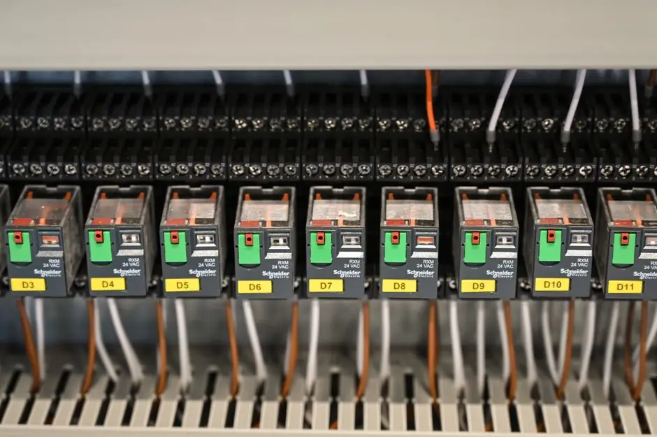
A selector switch is a manually operated control device that lets an operator choose between defined circuit states or machine modes; the rotation, key, or toggle is just the human interface, while the contact block behind the panel decides what the circuit actually does [S2].
The fastest way to mis-specify one is to choose by the knob alone. A 22 mm panel-mount maintained rotary with a 10 A thermal current and one million mechanical operations is a common industrial baseline, but the same physical device can be unfit for a motor load if the declared utilization category does not cover it [S1][S3].
The Four-Layer Selection Map
Treat a selector switch selection as four independent questions, because a phrase like "three-position selector" only answers one of them [S2].
Layer one is the operator: rotary knob, long handle, toggle lever, or key operator; the choice is set by what the operator must read at a glance (for example HAND-OFF-AUTO or LOCAL-REMOTE labels) and whether unauthorized change must be blocked [S2].
Layer two is positions and action: number of detents (commonly 2 or 3, sometimes more), and whether each detent is maintained, spring-return to center, spring-return to one side, or mixed (a common mixed form is maintained center with momentary sides, used for jog commands) [S2].
Layer three is contact logic: which circuits open, close, or change over in each position, expressed as a position-to-contact table using normally open (NO), normally closed (NC), and changeover (CO) blocks. Stack multiple blocks or use a cam program for complex functions [S1][S2].
Layer four is electrical duty: is the switch feeding a PLC input, a relay or contactor coil, a signalling circuit, or carrying the declared load directly? The answer sets the required utilization category and contact rating, which is why a switch that is fine for a 24 VDC PLC input can fail quickly on a 230 VAC motor circuit [S2].
Operator Style: Rotary Versus Toggle
Rotary selectors use a knob or handle that turns through defined positions and are preferred when panel markings such as HAND-OFF-AUTO, LOCAL-REMOTE, or 1-0-2 need to remain visually clear [S2].
Toggle selectors use a lever that flips between positions and give a compact, decisive human interface for simple state selection; they can be maintained, momentary, center-off, single-pole, or multi-pole depending on the exact device [S2].
The front operator does not prove electrical capability. A toggle lever is not automatically low-current, and a rotary handle is not automatically suited to power switching, so compare the declared contact arrangement and ratings rather than the look of the knob [S2]. The same panel face can be built two ways: modular contact blocks snapped on behind a rotary operator, or a shaft-and-cam stack that coordinates several circuits; both rotate, but the selection process and the contact duty differ [S2].
Action: Maintained, Spring-Return, and Mixed

Action is independent of whether the front mechanism is rotary or toggle. A maintained selector stays in the position where the operator left it, which makes it the right pick for long-term settings like On/Off, Auto/Manual, or Local/Remote where the visible state must persist [S1][S2].
Spring-return to center is the right pick for temporary commands such as jog, raise/lower, or a momentary request, because releasing the lever must remove the command, not latch it on [S2].
Mixed action combines both, for example a maintained center with momentary left and right, which is a common way to get a mode-select plus jog from one device [S2]. Using a maintained switch in place of a momentary one for a jog function is a classic spec error and a known cause of runaway or overheating faults, including in domestic oven controls where the selector carries heater current [S4].
Electrical Duty and Contact Ratings
Industrial 22 mm selector switches are commonly rated around 10 A thermal current with a mechanical life near one million operations, and the typical environmental rating for panel-front ingress protection is IP65 [S3].
Those headline numbers are not load-switching ratings. Thermal current tells you the continuous carry limit, not what the contacts can make or break under load, and the device will need an explicit utilization category (AC-15 / AC-12 / DC-13 class style duty) if it is asked to switch coils, motors, or heaters directly [S2][S3].
For control duty, a switch can feed a PLC discrete input (commonly 24 VDC at low current) or a contactor coil (commonly 24 VDC or 110-230 VAC at a few VA) without the contact block ever seeing the load. For declared direct load duty, the switch must carry and break the load itself, and the rating must be matched to the load type and inrush [S2].
Common Failure Modes and What They Tell the Buyer
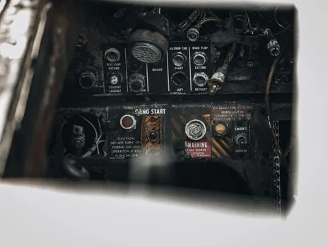
Overheating, loose terminations, and contact welding from switching the wrong load type are the dominant field failure modes for selector switches carrying real power, and they are usually a sign of a duty-mismatch rather than a bad part [S4].
When a selector is asked to break a load it is not rated for, the contacts can weld, stick, or progressively burn until the resistance rises and the terminals overheat, with the failure often showing up first as discoloration at the back of the switch and then as an open circuit when the contact finally lets go [S4].
Loose screw or push-on terminations are the second cluster, and they show up as intermittent operation, voltage drop under load, or heat at the terminal; the fix is mechanical (torque to spec, use ferrules on stranded wire) rather than electrical [S4]. Specifying a higher-rated switch does not save a loose joint; it only delays the symptom.
Standards, Cutouts, and Panel Integration
The de facto panel cutout for industrial selector switches is 22 mm, with 30 mm used on heavier legacy panels; choosing a 30 mm device when the cabinet is drilled for 22 mm, or vice versa, is a common late-stage error [S1][S3].
For control panels feeding machine safety, IEC 60204-1 and NFPA 79 set the colour convention for adjacent indicator lights, red for abnormal or fault, amber for warning, green for normal operation, blue for mandatory action, white for neutral or power available, which is why a selector switch paired with red/green lamps reads correctly only if the colour follows the convention [S3].
Ingress protection is split: the panel-front face is typically IP65 for industrial 22 mm devices, while the back of the switch (contacts and terminals) is only sealed to the panel by the gasket on the bezel, so a switch mounted on a poorly flat panel can lose its front rating without anyone touching the contacts [S3].
Who Should Pick Which Variant
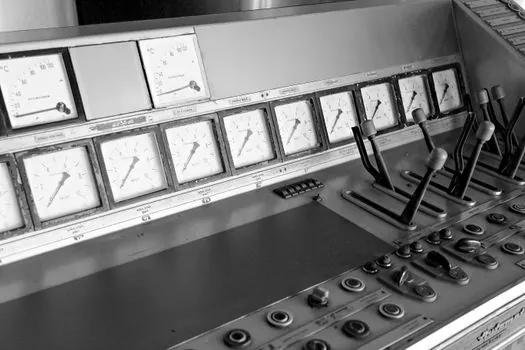
For a PLC-driven mode select (Auto/Manual, Local/Remote, Hand/Off/Auto) on a control panel, the mainstream pick is a maintained 22 mm rotary selector with modular 10 A thermal contact blocks, IP65 front, and snap-on NO/NC blocks configured for low-current control duty; this covers the majority of factory-automation panels [S1][S2][S3].
For a direct motor or heater load (for example a fan, a pump, or a domestic-style appliance heater), the right pick is a switch declared for that utilization category at the actual voltage and current, with a key or guarded knob if unauthorized operation is a risk; a general-purpose 10 A control-duty switch used as a direct load switch is a known failure path [S2][S4].
For jog or inch commands, use a spring-return (momentary) device, not a maintained one, even if the front looks similar; for tamper-resistant mode select, use a key-operated device, not just a generic knob [S1][S2].
Shortlist Logic and Sourcing Signals
Build the shortlist from four documented answers: operator style and access (knob/lever/key), position and action table (number of detents and which are maintained or spring-return), contact logic (NO/NC/CO per position, in a written table), and electrical duty (PLC input, coil, or direct load, with the matching utilization category) [S2].
Trackable signals to watch on supplier documentation: declared utilization category on the datasheet (not just thermal current), mechanical and electrical life curves, IP rating of the assembled front face, and a parts list for replacement contact blocks and lamps so a failed contact can be swapped without scrapping the whole operator [S3]. For adjacent product decisions, see the pushbutton and pilot light combos spec path and the broader industrial switch selection guide, and use the limit switch duty map when the selector has to work alongside a position-feedback device.
For component-level specifications, see selector switch.