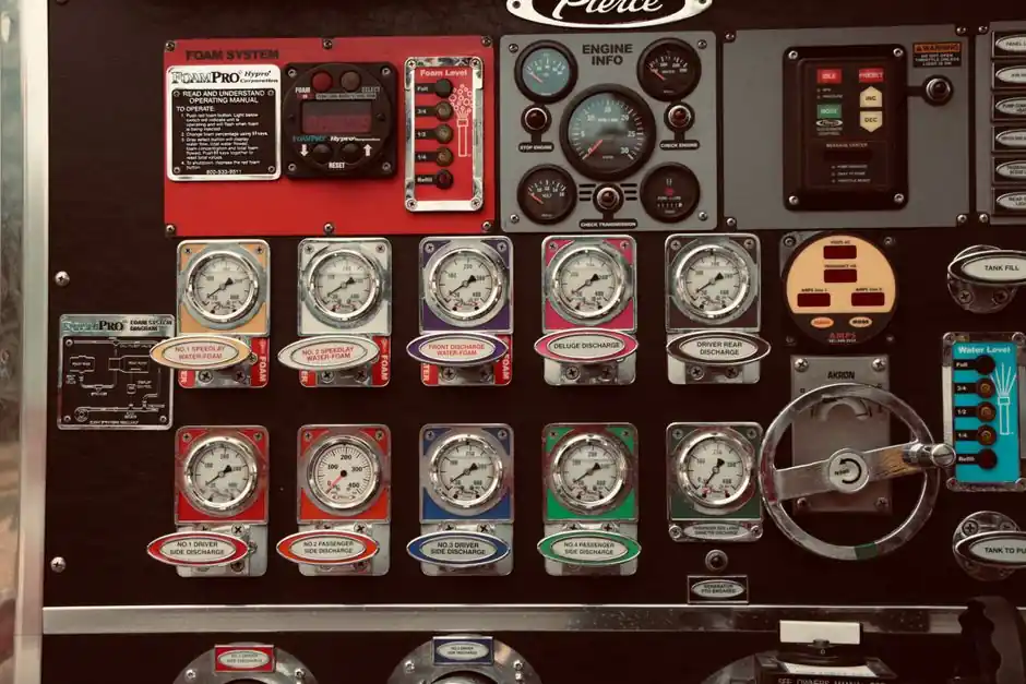
A selector switch is a hand-operated device that opens, closes, or reroutes electrical circuits, with common 22 mm and 30 mm panel cutouts being the dominant industrial mounting standards for control desks and operator panels [S1].
Selection is a four-step sequence: define operator duty, pick the bezel size, choose the action type, then verify the contact block configuration, ratings, and enclosure for the installation environment [S1][S2].
Selector Switch Scope vs Disconnect and Transfer Switches
Selector switches are operator-interface control devices, not isolation devices: their job is to choose a machine state such as Auto/Manual, Forward/Reverse, or Local/Remote, and they do not provide lockable isolation of hazardous energy on their own [S1].
Disconnect switches are manually operated safety devices whose primary function is mechanical isolation of the load from the power source with a visible break, and in the U.S. they must meet NEC Article 430 sizing and OSHA 1910.147 lockout/tagout requirements; a 600 A+ service-entrance disconnect in an industrial plant is a typical large-frame example, while a 30 A conveyor isolation switch illustrates the small-frame end of the range [S2].
Generator transfer switches are a separate equipment family: they select between utility and generator sources while preventing paralleling, with the choice between manual transfer (portable gen) and ATS (permanent standby) driven by generator type, load scope, current, phase, neutral, fault rating, controls, and the locally adopted installation rules [S3]. The three families overlap only at the contact-block and current-rating layer, so mixing them up in a spec is a common drafting error.
Cutout and Bezel: 16 mm / 22 mm / 30 mm Decision Map
Standard mounting cutouts of 22 mm and 30 mm dominate factory panels, with 16 mm reserved for compact or handheld equipment, and the bezel size fixes the matching contact block, legend plate, and key-actuator accessories from the same product family [S1].
22 mm is the most common global industrial size, balancing ergonomic knob/lever area with panel density. 30 mm is the heavy-industrial default in North American machinery lines, giving more finger room for gloved operators and a wider range of key-lock and illuminated actuators. A 16 mm device makes sense only where panel real estate is constrained, such as a small benchtop instrument, and should not be specified for line-of-sight production-floor control where a 22 mm minimum is the safer call. For full bezel and cutout geometry across the related pilot-device family, see the 16/22/30 mm selection map.
If the panel already uses push buttons, illuminated pilots, and selector switches from the same vendor family, stay on the same cutout standard. Mixing 22 mm and 30 mm in one operator console forces two stocking SKUs for legend plates and contact blocks, which is rarely worth the ergonomic trade.
Maintained vs Momentary vs Key-Operated: Matching the Operator's Intent

Maintained (stay-put) selector switches hold the chosen position until the operator changes it again, making them correct for Auto/Manual, Hand/Off/Auto, and On/Off mode selection where the state must persist without continuous finger pressure [S1].
Momentary (spring-return) selectors snap back to a default position the moment the operator releases the knob, and are the right call for short-duration commands such as Jog, Test, or Reset where the machine should fall back to a safe state if the operator's hand leaves the device [S1]. A push button gives the same momentary behaviour but resets itself by spring only; a momentary selector adds a maintained default position plus a spring-returned alternate position, which is a different control-language signal to the operator.
Key-operated maintained switches restrict who can change the mode, which is the right pick for Source 1/Source 2 selection, Bypass mode, or any setting where an unauthorised change is a safety or process-risk event. The comparison below lines the three options against the most common selection criteria:
Action type vs selection criteria: Maintained for persistent mode (Auto/Manual, HOA); Momentary for spring-returned commands (Jog, Test, Reset); Key-operated maintained for access-restricted mode (Source transfer, Bypass, Service). For multi-position HOA, LOR, or Forward/Reverse/Stop logic, the maintained type dominates. For E-Stop command leg switching on a maintenance loop where a fallen hand must default the machine to safe, the momentary type is the right engineering call.
Push buttons are not a substitute for any of the three: a push button only delivers a temporary signal, so specifying a push button for Auto/Manual selection is a control-language mistake, not a preference call [S1].
Contact Block Configuration: Poles, Throws, and NO/NC Logic
Contact blocks carry the electrical work of the switch and can be specified as normally open (NO), normally closed (NC), or changeover, with the block pattern chosen so the switch position matches the logic the PLC or relay coil expects [S1].
Most industrial 22 mm and 30 mm selector switches accept stacked contact blocks, so a two- or three-position switch can deliver multiple isolated circuits in one device. A 3-position selector (Hand/Off/Auto) commonly needs two blocks: one NO for the Hand output and one NO for the Auto output, sharing a common return, with the Off position opening both. If the Off position must also drop out a contactor, an early-make/late-break NC block is added to ensure the stop circuit asserts before the run circuits close, which is a common sequencing requirement on motor starters.
Mechanical interlock and overlap specifications are also set at the contact-block layer: overlap (make-before-break) keeps one circuit closed while the next closes, useful for transfer between two running sources; non-overlap (break-before-make) guarantees an open circuit between positions, which is the safer default for a Forward/Reverse switch where overlapping would short the direction contactors. For the wider pilot-device combo logic (pilot lights, dual push buttons, combined assemblies), see Pushbutton and Pilot Light Combos: Specs, Zones, and Sizing.
Electrical Ratings: Matching the Block to the Real Load
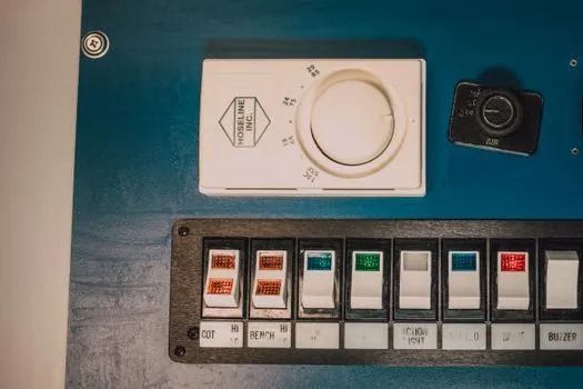
Selector switch contact blocks are typically rated by their design letters (AC-15 / AC-12 for inductive / resistive AC control duty, DC-13 for inductive DC), and a block that handles 6 A at 230 V AC on a heater circuit is not automatically rated for the same 6 A on a 24 V DC solenoid coil, because DC inductive loads arc more aggressively on contact break. [S1]
For a low-current PLC input, a block rated for 5 mA at 5 V is the realistic minimum, because standard silver-alloy contacts can fail to make at the low end of their curve. For a 110 V AC relay coil, an AC-15-rated block at 6 A is the common pick. For a 24 V DC indicator lamp or solenoid, DC-13 duty is the spec to require, not just a generic 6 A contact. Treating the contact block rating as interchangeable across AC and DC loads is one of the fastest ways to fail an inspection or burn out a contact.
For motor circuits, NEC 430.109 mandates that a motor disconnect carry both an ampere rating and an HP rating, so a selector switch used as a motor disconnect must be UL 98-listed as a motor-rated device; a standard pilot-device selector switch is not a substitute [S2]. This is the cleanest boundary line between a pilot-device selector switch and a disconnect, and it should appear in the spec text: the operator-interface selector switch controls the circuit, the listed disconnect isolates it.
Environment, Enclosure, and Ingress
Front-element ingress protection for panel-mounted selector switches is commonly stated as IP65 (dust-tight, water-jet resistant) or IP66 for washdown areas, while the enclosure behind the panel must be specified separately to match the room, not the front face of the switch. [S2]
For a food-and-beverage line with daily hose-down, IP66 or IP67 on the operator face plus a stainless-steel bezel is the realistic minimum. For an indoor control cabinet in a climate-controlled room, IP54 on the face and a NEMA 1 / IP54 enclosure behind it is usually enough. For outdoor rooftop HVAC isolation, NEMA 3R or 4X on the enclosure keeps the whole assembly weatherproof. The temptation to specify IP66 for everything is wasted money, while specifying IP54 on a washdown floor is a maintenance failure waiting to happen.
Temperature, chemicals, and UV drive the bezel and actuator material choice: polyamide for indoor general duty, metal (zinc alloy or stainless) for impact and chemical exposure, and silicone-rubber boots for very dirty or food-grade surfaces. Illuminated selectors add a lamp or LED module in the centre of the actuator, and the LED voltage must be specified to match the control power supply (typically 24 V DC, 110 V AC, or 230 V AC).
Standards, Certification, and Sourcing Signals
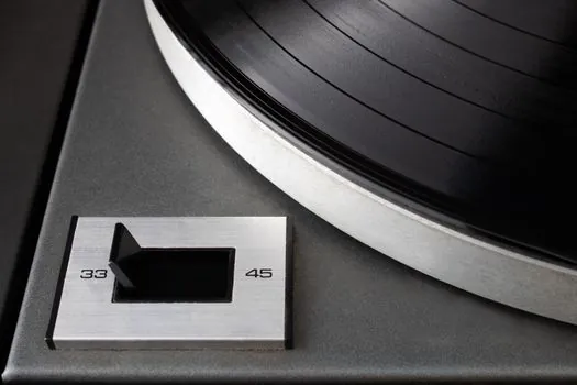
Industrial selector switches used in machinery typically carry IEC 60947-5-1 conformity for low-voltage switchgear and controlgear (including the AC-15 / DC-13 utilization categories named above), UL 508 for industrial control equipment in North America, and where the switch is the motor disconnect, UL 98 [S2].
For hazardous locations, the relevant framework is the IEC 60079 / ATEX 114 (Directive 2014/34/EU) or NEC Class/Division system: pilot-device selector switches used inside a Zone 1 or Zone 2 enclosure must be certified as part of the panel, not on their own. If the spec is a push button, pilot light, and selector switch all sourced from one vendor family, the part numbers fall inside one certification umbrella, which is the cleanest way to keep the documentation coherent. For the vendor and part-number bands across 16/22/30 mm families, see Pushbutton & Pilot Light Suppliers: 16/22/30 mm Vendor Map and Spec Bands for 2026.
Two trackable signals for the next six months: harmonisation of IEC 60947-5-1 with the latest low-voltage switchgear updates, and the gradual displacement of traditional incandescent-illuminated selectors with integrated 24 V DC LED modules on most new machine builds.
For component-level specifications, see selector switch, linear guide, and crossed roller guide.