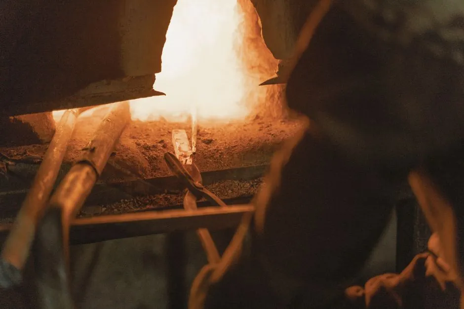
Electronics housings, whether aluminum smartphone frames, zinc die-cast connector shells, or copper heat-spreader lids, demand a tighter melt-purity window than most general foundry work, and a medium-frequency (1-20 kHz) coreless induction furnace in the 100-500 kg capacity class is the default specification for production runs above roughly 200 kg/shift [S4][S5].
Capacity brackets for induction melting equipment span from sub-1 kg laboratory units to 100 t utility furnaces, with the dominant electronics-housing build size sitting between 50 kg and 1 t per batch [S6]. Furnace builders active in 2026 list parallel offerings for IGBT medium-frequency melting of steel, stainless steel, copper, aluminum, gold, and silver, with matched scrap-recycling and automatic ingot-casting auxiliaries on the same control platform [S5].
Why medium-frequency coreless, not line-frequency or channel-type
Coreless medium-frequency melting furnace designs operate in the 1-20 kHz band, which forces electromagnetic stirring in the bath and enables melt-rate control within roughly ±5%, the level electronics-housing die-casters need for repeatable shot weight [S5]. Channel-type (submerged-heel) induction units hold a residual heel that makes alloy changeover slow, a non-starter for plants running 3-4 housing alloys per week. Coreless designs also tolerate full drain, so melt contamination between an AlSi9Cu3 run and a ZnAl4 batch is mechanically impossible rather than procedurally managed. Line-frequency (50/60 Hz) mains-frequency coreless furnaces exist but require laminated iron yokes and bulkier compensating capacitors for the same kW output, raising the floor footprint per kg of melt by an order of magnitude, which is why mid-volume electronics foundries standardise on MF or HF units instead [S2].
Melt-rate, power density and crucible selection
Typical industrial MF coreless furnaces for the 100-500 kg class run at 100-500 kW input, with specific power around 0.5-1.5 kW per kg of molten aluminum held, giving a cold-start melt time of 45-75 minutes for a 250 kg AlSi9Cu3 charge [S4]. A practical rule of thumb: silicon-carbide crucibles suit zinc and lead below 800 °C, while alumina or magnesia-spinel grades are mandatory above 1100 °C for aluminum, and fused-silica or isostatically-pressed magnesia is the standard pick for copper above 1200 °C [S6]. For the crucible furnace geometry that most housing foundries use, crucible wall thickness is typically 20-40 mm for a 250 kg Al unit, and water-cooled copper coil sections (often rectangular tubing, 15-25 mm bore) sit concentric to the crucible with a 10-30 mm annular refractory gap [S3].
Atmosphere control and clean-melt requirements
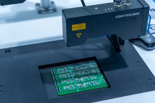
Electronics housings fail surface-finish audits long before they fail structural tests, so melt-degas and inclusion control dominate the spec sheet. Inert-atmosphere or vacuum holding furnace modules on the pour line typically run oxygen below 50 ppm, with dew point held at -40 °C or lower when magnesium-bearing aluminum alloys are processed. Shaft degassers using argon or nitrogen at 0.5-1.5 L/min per kg of melt, plus rotary impeller speeds of 300-600 rpm, are the default fluxless route for housing-grade alloys. For back-end protection, sealed transfer ladles with graphite stoppers and electromagnetic pumps prevent reoxidation during the pour into the cold-chamber die-casting machine, an important step because Al2O3 bifilm content above roughly 10 ppm correlates with visible blistering after anodizing. [S3]
Power electronics, cooling and EMC containment
The 2026 IGBT medium-frequency converter stacks at the major Chinese OEMs are typically 10-50 kHz switching with 1200-1700 V IGBT modules, water-cooled heatsinks, and a DC bus capacitance sized at roughly 2-4 µF per kW of output [S5]. Coil-side cooling is the bottleneck: deionized water at 0.2-0.4 MPa, conductivity below 5 µS/cm, with flow interlocks that trip the rectifier if cooling water drops below the manufacturer-set limit (often 15-25 L/min per coil section) [S3]. For plants co-located with SMT lines or RF test cells, the practical gating factor is radiated EMC: an unshielded MF furnace can emit broadband 9 kHz-30 MHz noise that disrupts nearby EMC compliance benches, so the procurement spec must include a Faraday-cage coil enclosure, filtered power feeders, and a documented 30 MHz-1 GHz radiated-emissions test, rather than the supplier's generic "industrial-grade shielding" claim.
Spare-parts readiness and OEM aftermarket

Inductotherm, AJAX-TOCCO, Electrotherm, Megatherm, and Pillar are the legacy names that still dominate the installed base in this segment, and the third-party spares ecosystem (SCR modules, rectifier diodes, inverter cards, snubber assemblies, water-cooled power cables, chill blocks, current-limiting reactors) is mature enough that single-component lead times are typically 2-6 weeks for Indian, EU, and East Asian distributors [S3]. The specific components most exposed to wear are the coil's inner-liner refractory, water-cooled power cables at the coil-to-bus transition, and the snubber capacitors across the SCR stacks, and stocking 1× replacement of each is the minimum holding for a continuous-shift housing line [S3]. Generic equivalent part numbers such as the 9102/9112 inverter SCR, 1137 inverter diode, and C431PM rectifier SCR give the maintenance team a cross-reference map independent of the original OEM [S3].
Comparison: furnace type vs housing-alloy fit
Three configurations cover virtually all electronics-housing production, and the choice falls on alloy mix, not on furnace cost alone. A coreless MF unit in the 100-500 kg class is the right call for plants that run 3+ housing alloys and value changeover speed. A vacuum or pressurized induction heat treatment furnace module, in the same 100-500 kg class but with a sealed cold-wall crucible, is the only realistic route for magnesium-housing production or for oxygen-sensitive copper heat-spreader alloys, at a 2-3× capital premium over atmospheric MF but with melt hydrogen below 2 ppm routinely achievable. For most housing foundries that run a mixed Al / Zn / Cu work envelope, the spec is the atmospheric MF coreless unit, the vacuum unit is reserved for the specific alloy that cannot be processed any other way. [S1]
Procurement checklist and what to ask the vendor
Five items separate a usable quotation from a marketing one. First, the rated melt rate in kg/h for the specific housing alloy, not a generic "for steel" figure, because AlSi9Cu3 and ZnAl4 melt rates differ by 30-50% on the same kW input. Second, the specific power consumption in kWh per ton of liquid aluminum, which for a well-tuned 250 kW MF coreless unit should sit at 540-600 kWh/t and is a direct proxy for coil-coupling efficiency. Third, the documented EMC emissions profile to CISPR 11 Class A or the local equivalent, with the test report dated within 24 months of the quotation. Fourth, the cooling-water specification in writing: pressure range, conductivity ceiling, flow interlock threshold per coil section, and the materials of construction for wetted parts. Fifth, the cupola furnace alternative is irrelevant for housing work, but the vendor should still be able to explain why MF induction beats gas-fired or resistance heating for the buyer's alloy mix, because the answer exposes how much real melt-metallurgy experience sits behind the sales team. [S3]
Trackable signals over the next quarter: IGBT medium-frequency converter pricing as 1200 V vs 1700 V silicon supply normalises after 2025-2026 capacity expansion, and the rollout of closed-loop optical-emission melt-chemistry probes that cut spectrographic lab work by 50% or more on AlSi housing lines. For a parallel read on how the same MF coreless architecture is specified for a different end-use, see the spec map for induction furnace selection for hardware manufacturing and the aerospace-focused induction furnace selection for aerospace components writeup, both of which use the same kW-per-kg and crucible-grade logic but with different alloy and cleanliness gates.