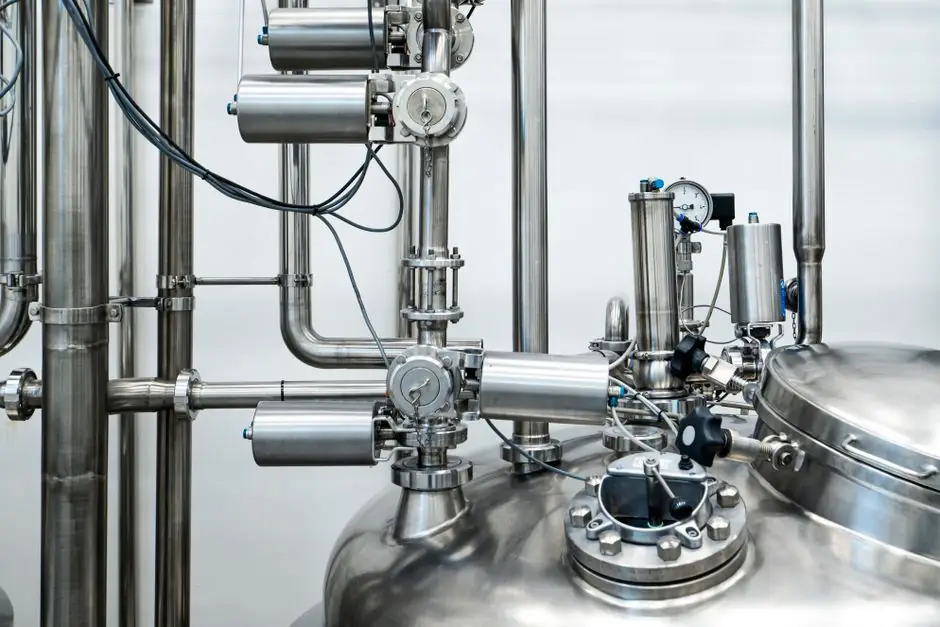
An industrial refrigeration system removes heat via a closed thermodynamic loop of compression, condensation, expansion and evaporation, with each stage demanding matched hardware rather than off-the-shelf HVAC units [S1]. The dominant industrial duty profile is high-load, 24/7 continuous operation across cold storage, food processing, chemical manufacturing and pharmaceutical facilities, and this is what differentiates it from commercial refrigeration built for intermittent retail duty [S3].
Capacity bands stretch from small monoblock units for compact cold rooms to large-scale screw chiller arrays and ultra-low-temperature industrial freezers, with screw chillers flagged as the mainstream choice for industrial scenarios because of their modular expandability, stable high cooling output and lower daily maintenance cost [S3]. Sizing must be driven by process load, ambient wet-bulb temperature, and the refrigerant's thermodynamic envelope, not by nameplate cooling capacity alone [S4].
Compressor Selection: Matching Type to Capacity and Refrigerant
Compressors handle refrigerant in its gaseous state and raise both pressure and temperature, so the choice of technology sets the upper ceiling on efficiency, noise and turndown [S1]. The industrial compressor menu breaks into six practical families: piston, screw, scroll, helical-screw, hermetic and semi-hermetic, with semi-hermetic units rated for high-temperature performance and low evaporating temperatures down to -40 °C (-40 °F) [S1].
Reciprocating (piston) compressors remain common and versatile across a wide capacity envelope, screw compressors are favored for large-scale continuous duty due to durability and high-load efficiency, and scroll units are typically specified for medium-capacity applications where quiet operation matters [S4]. Helical-screw and standard screw designs are explicitly targeted at HCFC/CFC refrigerants and emphasize energy saving, while the brands most often benchmarked in industrial builds include GEA, Bitzer and Copeland-Emerson [S1].
Condenser Configuration: Air, Water, or Evaporative
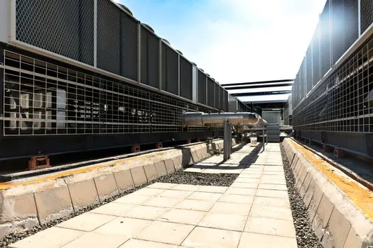
The condenser rejects the heat absorbed from the process plus the heat added by compression, and selection is dictated by water availability, ambient conditions and site footprint [S4]. Three configurations dominate: air-cooled condensers using forced-draft fans (simpler install where water is scarce), water-cooled condensers paired with a cooling tower (typically higher heat-rejection efficiency), and evaporative condensers that combine air and water for high efficiency in dry climates [S4].
When a condenser is packaged with a ventilating motor and a compressor into a single skid, the assembly is sold as a condensing unit, a common building block for distributed industrial plants [S1]. For larger projects, two condenser brands repeatedly surface in industrial specifications: SPX Cooling Technologies for evaporative designs and Krack for unit-level condensing skids [S1]. Heat-rejection sizing must reconcile the compressor's full-load waste heat with the design wet-bulb temperature at the installation site, otherwise the high-side pressure safety controls will throttle capacity in summer.
Evaporator and Expansion Stage: Where Cooling Actually Happens
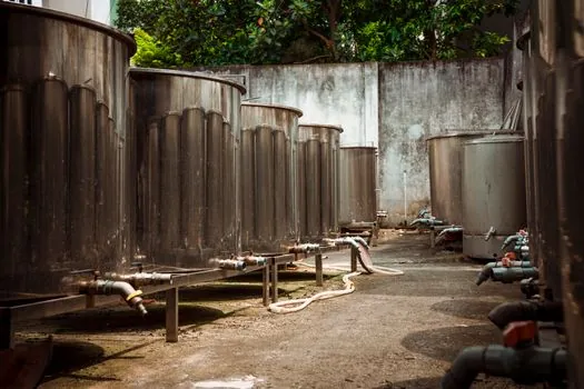
The evaporator is the point where the refrigerant absorbs process heat and boils at low pressure, and its design has a direct multiplier on system efficiency and product quality [S4]. For food and pharmaceutical cold rooms, air-handling units with finned coils and EC fans are the default, while plate or shell-and-coil evaporators are used where the load is a process liquid or glycol secondary loop.
Expansion devices control the pressure drop from high-side liquid to low-side two-phase, with thermostatic expansion valves (TXV) and electronic expansion valves (EEV) the two main options; EEVs are increasingly specified on new builds because they modulate with superheat and tolerate wider operating windows than a fixed-orifice TXV. The whole loop is held inside the crossed roller guide of mechanical tolerances that a process engineer has to keep tight, from suction superheat at the evaporator outlet to subcooling at the condenser liquid line.
Manufacturer Map: Pumps, Compressors and System Integrators
The U.S. commercial and industrial refrigeration supply chain separates cleanly into three groups: pump specialists, compressor OEMs, and full system integrators. The pump side is led by names such as Grundfos Centrifugal (high-efficiency stainless centrifugal pumps for HVAC, cold storage and food processing), Viking Pumps (positive displacement), MTH Pumps, Goulds Centrifugal, Barmesa Centrifugal, Barnes Submersible, Deming Centrifugal, Goulds Submersible, and Pulsafeeder Dosing [S2].
On the compression side, Busch Compressors is the dedicated refrigeration player in the same shortlist, while GEA, Bitzer and Copeland-Emerson anchor the industrial compressor tier [S1][S2]. For a spec-first sourcing map that extends to chiller skid builders and U.S. system integrators, the Industrial Chiller Suppliers spec-first map is a useful cross-reference when the refrigeration package is delivered as a chiller rather than a field-built plant room.
Direct vs Indirect Systems and Refrigerant Choice
A direct (DX) refrigeration system expands refrigerant inside the space or coil being cooled, while an indirect system uses a secondary loop (typically glycol or brine) with a chiller or refrigeration plant on one side and remote heat exchangers on the other [S4]. Indirect systems are preferred where the load is distributed across a large facility, where leak risk must be confined to a plant room, or where the cold rooms must hold different temperature setpoints on a common primary loop. Direct systems win on first cost and thermodynamic efficiency for single-room or single-process loads.
Refrigerant choice now sits inside a global regulatory envelope. The market shift is toward natural and low-GWP refrigerants (CO2/R744, ammonia/R717, and HFOs such as R-1234ze and R-513A), with ammonia dominant in large cold storage and food processing plants and CO2 cascade systems used for ultra-low-temperature duty below -40 °C [S4]. Selection must weigh GWP, ODP, toxicity class, flammability class (A1, A2L, A3 under ISO 817), and charge-size limits dictated by the occupied space.
Efficiency Levers: VFDs, Heat Recovery and Controls
The biggest efficiency levers on an existing industrial refrigeration plant are variable-frequency drives on screw and centrifugal compressors (typical turndown 25–100% of full load), floating head pressure control matched to ambient wet-bulb, and electronic expansion valves on the low side [S4]. Heat-recovery desuperheaters on the compressor discharge can supply 60–80 °C hot water for cleaning or space heating, recovering a meaningful share of the compressor's waste heat without adding a separate boiler.
Smart controls, the Industry 4.0 layer, add real-time suction and discharge pressure trending, refrigerant leak detection, and predictive maintenance on compressor motor current and bearing vibration, which collectively cut unscheduled downtime and tighten food-safety audit trails [S4]. The same control philosophy of layered sensors and condition monitoring shows up in non-thermal process plants, and the spec patterns used to select NDT equipment for pressure-vessel inspection transfer cleanly to a refrigeration pressure-vessel integrity program.
Installation, Maintenance and Safety Protocols
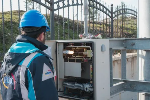
Professional installation starts with a load calculation against the design ambient, then welded or brazed high-integrity piping (no push-fit fittings on the high side), proper oil management, and a nitrogen pressure test before refrigerant charging. A baseline preventative maintenance schedule typically includes quarterly coil cleaning, annual compressor oil analysis, annual leak checks on the entire refrigerant loop, and a five-yearly pressure-vessel recertification where local codes apply [S4].
Safety is not optional on an industrial refrigeration plant. Ammonia plants must comply with IIAR standards including IIAR 2 (equipment), IIAR 6 (piping) and IIAR 9 (refrigeration machinery room ventilation), while CO2 systems need high-pressure relief per the applicable pressure-vessel code, and HFC/HFO plants follow ASHRAE 15 with charge limits per occupancy classification. For facilities that need to integrate process cooling with general plant air, water, or inert gas, the spec patterns used to lay out an industrial fastener production line illustrate how staged utility planning reduces retrofit cost.
The next decision nodes for any industrial refrigeration spec are the same three: lock the refrigerant (which drives the entire component stack and code path), lock the compressor family against the load profile (reciprocating for flexibility, screw for 24/7 high-load, scroll for mid-capacity), and lock the condenser against ambient water availability. A plant that has all three pinned before the first purchase order will outbid and outperform one that buys around nameplate cooling tonnage, and the same source-by-spec discipline applies to construction machinery and equipment selection on the civil side of a cold-storage build.