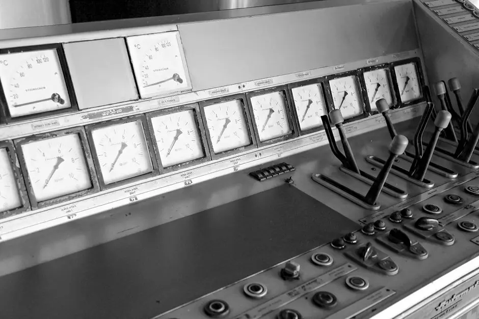
Modern zinc-ingot lines run as three linked control islands, dosing control, furnace control, and ingot-line control, all feeding an integrated automation layer that sequences melt, pour, and demould [S2].
The hottest instrumentation work in 2023-2026 is the slag pick: Adams and MATLAB joint-control work on a zinc-alloy slag-picking robot showed an improved nonlinear PID outperforming classical PID and fuzzy-PID on joint angular-velocity tracking [S1].
Core process variables and sensor points
The three physical variables a zinc-ingot line must hold tight are melt temperature, bath level in the holding or galvanizing pot, and dross mass generation rate, all read by thermocouples, laser or guided-wave radar level probes, and load-cell weight modules on the launder and ladle [S2]. A typical primary zinc melt sits at 419-430 C (the pure zinc melting point is 419.5 C) and is usually held in a 30-80 t induction or electric-resistance furnace with silicon-carbide or fiber-insulated launders; even a 5 C excursion drives measurable dross growth, so most modern lines run dual-element Type-K sheathed thermocouples with a redundant transmitter per furnace zone [S5].
Process calibration discipline matters here because the temperature window is narrow: pyrometers are avoided in the slag zone (oxide skin blocks IR) and instead immersion thermocouples in silicon-carbide sheaths are the workhorse, with a 12-24 month replacement cycle in aggressive galvanizing pots [S2]. For hoisting and feeding, the lifting cycle of a single ingot into the pot typically runs 0.5-1.5 hours per manual cycle, which is why automated hoists with continuous-feed conveyors are replacing gourd-hook chains [S4]. See the process control reference for the loop-architecture context, and the process calibration reference for thermocouple drift and field-trim procedures on melt-temperature loops.
Automation architecture: three subsystems, one SCADA
An integrated zinc-melt-and-cast automation system is conventionally split into dosing control, furnace control, and ingot-line control, each as a PLC island talking to a central SCADA over industrial Ethernet [S2]. The dosing island weighs the alloying additions (Al, Cu, Mg) on loss-in-weight feeders and cross-checks against a target Zn-99.995% or Zn-99.99% grade before ladle dispatch.
The furnace island runs cascaded temperature control, outer loop on bath TC, inner loop on SCR-fired electrode or burner valve, with a typical loop time of 2-5 s and a furnace-pressure trim loop on the induced-draft damper. The ingot-line island sequences the constant-volume pouring ladle, the chain or belt casting conveyor, the water-spray cooling section, and the automatic stripping/stacking robot, with safety interlocks on ladle tilt, water flow, and chain speed [S5]. This kind of three-island split is standard across non-ferrous casting lines and pairs naturally with Ethernet-APL or PROFINET backbones to the HMI.
Slag and dross handling: from manual rabble to PID-controlled robot
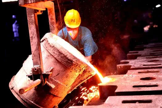
Slagging is consistently flagged as the most labour-intensive and health-hostile step on a legacy zinc-ingot line, with manual rabbling exposing workers to zinc oxide fume, and most domestic Chinese smelters were still running manual slag removal as of 2023 [S1]. The control problem is a multivariable one: the slag crust thickness, the crust's break-line position, and the bath-level setpoint all interact through the slag-rake toolpath.
The IEEE 2023 simulation study (Tao Qin et al., ISCER 2023, Hangzhou, 17-19 February 2023, DOI 10.1109/ISCER58777.2023.00022) compared three joint-control strategies on a six-DOF slag-picking arm: classical PID, fuzzy-rule PID, and an improved nonlinear PID. The improved nonlinear PID gave the lowest joint-angular-velocity tracking error and the most stable end-effector trajectory across a simulated dross layer of 10-40 mm thickness [S1]. The same logic is now being retrofitted onto purpose-built dross skimmers rather than adapted general-purpose articulated robots, because a galvanised-pot slag layer behaves very differently from a foundry-floor pour.
Hot-dip galvanizing: premelted ingot addition and pot-level control
For galvanizing lines the control target is more subtle: not just casting yield but pot-temperature stability, because coil entry into a 450-460 C zinc bath pulls a 20-40 C transient that the level-control loop must absorb. Chinese patent CN102392206A (ANSC-TKS Galvanizing, filed 2011-11-11, published 2012-03-28) describes a premelted-ingot dosing method that floats the zinc ingot in a pre-heat bay before submerging it into the pot, with a floating body and electric pre-heat stage to cut the thermal shock to the working bath [S3].
The complementary problem, continuous addition of cold ingots causing bath-level oscillation, is addressed by patent CN110952055A (WISDRI Engineering & Research, published 2020-04-03): an automated hoisting and feeding system that lifts ingots on a gourd-track hoist, indexes them through a tilting feed seat, and submerges them at a controlled rate to keep the liquid-surface temperature stable. The patent's problem statement explicitly names "poor temperature control of the liquid surface of the zinc pot, the inability to achieve continuous zinc addition, and the labor intensity of workers" as the failure modes the design targets [S4]. A typical hoist cycle today is 0.5-1.5 hours between ingots, which the automated system compresses to a steady, demand-driven rate [S4].
Selection criteria for a new line vs retrofit
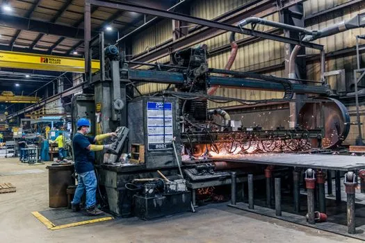
For a greenfield line, the spec map is: an electric or induction melting furnace of 30-80 t capacity, a constant-volume pouring ladle sized to 1-3 t per stroke, a chain or belt casting machine with 25-50 moulds per metre, and a stripping/stacking cell, all driven from a single PLC and SCADA pair with PROFIBUS or PROFINET I/O [S2][S5]. Greenfield buyers should also budget for a dross-recovery sub-loop: the dross can be 2-5% of charge weight, and recovering it through a dedicated rotary or reverb furnace pays back inside 18-30 months on a 50,000 t/y line.
For a retrofit on an existing galvanizing pot, the priority order is different: first add redundant immersion thermocouples and a radar level probe, then automate ingot hoist and feed (cycle compression from 0.5-1.5 h to demand-driven), then add a robotic dross skimmer only if manual slag-removal hours exceed 2 FTE per shift [S1][S4]. A zinc ingot casting line is functionally closer to a zinc die casting machine than to a steel continuous caster, and the control loop density, 1 temperature loop per furnace zone, 1 level loop per pot, 1 weight loop per ladle, matches what an experienced instrumentation engineer would expect on a non-ferrous die-cast cell rather than a primary smelter [S5].
Standards, failure modes, and trackable signals
No single ISO or IEC standard governs the entire zinc-ingot line, but the relevant stack is: ISO 752 for zinc-ingot grade definitions (SHG Zn-99.995%, HG Zn-99.99%), ASTM B6 for chemical composition, and IEC 61131-3 for PLC programming; emissions from dross handling are bounded by regional air-quality codes (CN GB 31573, EU IED) rather than a single global rule, so local permitting drives hood and baghouse design. Common failure modes the control system must catch are: thermocouple drift causing bath overheat, ladle-tilt sensor fault leading to short-pour, and launder-blockage pressure spike from frozen zinc (zinc solidifies at 419.5 C, so a 30-minute heater trip is enough to plug a 100 mm launder) [S2][S5].
Two trackable signals for the next quarter: (1) commercial release of a turnkey slag-picking cell based on the ISCER 2023 nonlinear-PID control law, beyond the simulation stage, and (2) wider roll-out of PROFINET-APL or Ethernet-APL field instruments on the bath-temperature loops, replacing the legacy 4-20 mA HART chains on retrofits. Spec-driven buyers who want a working shopping list should anchor on the same four items most engineering teams anchor on: the furnace temperature loop, the pot level loop, the ingot-feed hoist, and the dross skimmer, in that order.
This topic is covered further in Bulldozer Lifespan, Service Intervals and Replacement Guide.