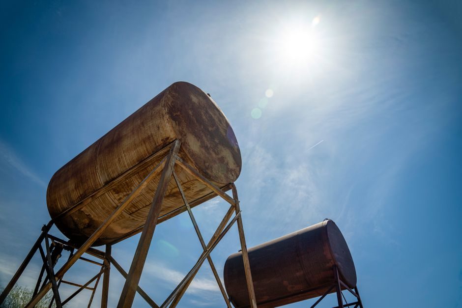
An ISO tank container is a cylindrical pressure or non-pressure vessel mounted inside a 20-ft ISO corner-casting frame, built to the ISO 1496/3 (Series 1 freight containers) dimensional envelope and approved under CSC for sea transport [S2]. Standard nominal capacity sits in the 21,000–26,000 L band, with 24,000 L (≈26 m³) the most common for a 20-ft frame, and tare weights typically 3,500–3,900 kg for stainless-steel units, leaving roughly 26–30 tonnes payload depending on product density [S2][S3].
For a process engineer, the datasheet is the only place the design code, material, MAWP, test pressure, lining and fitting schedule are all committed to paper. Treating that single A4 sheet as the binding specification — not the marketing flyer — is the difference between a chemical fleet that passes port-state inspection and one that is grounded for retest [S1][S2].
Frame Dimensions, CSC Plate and Corner Castings
Every 20-ft tank container must conform to ISO 1496/3 external dimensions: 6,058 mm length × 2,438 mm width × 2,591 mm height, with corner castings at the ISO 1161 pattern so it stacks in any ISO cell-slot [S2]. The CSC safety-approval plate (or ACEP plate for tank containers) is riveted to the door end and lists manufacturer, approval number, year of build, design code (ASME VIII Div 1, EN 14025, or CODAP), and the next periodic inspection due date — that date is what port-state control officers key off, not the build year [S2][S3].
A correct datasheet states overall length, width, height, wheel-base tie-rail centres and the exact corner-fitting spec (per ISO 1161); mismatches between datasheet and physical plate are the single most common reason buyers reject a used unit at survey [S3]. Pay close attention to gross weight (typically 36,000 kg for 20-ft ISO tanks) and stacking capability (192 kN corner-post load, i.e. 8 high stacked fully loaded) — these are not negotiable design inputs.
Design Codes, Material Grades and Lining Options
The vessel itself is built to one of three principal codes: ASME BPVC Section VIII Division 1 (U-stamp, common for US and global chemical service), EN 14025 (European, with the π-mark and TPED link for transportable pressure equipment), or CODAP (French) [S2]. Shell material is overwhelmingly 304 or 316/316L stainless steel for chemical and food service, with shell thicknesses typically 4–6 mm on a 24,000 L frame and head thickness rising to 5–8 mm depending on MAWP [S2][S3].
When the product attacks stainless — strong chlorides, hot concentrated acids, amines — the datasheet should show a rubber-lined (EPDM, butyl or natural rubber) or PTFE-lined barrel, and the lining specification (vulcanisation method, cure temperature, spark-test voltage) belongs on the same datasheet, not buried in a separate coating certificate [S3]. Comparison across the three principal barrel options: stainless 316L gives the best chemical range but the highest cost; rubber-lined carbon steel is the lowest cost for non-sensitive chemicals but cuts the operating temperature ceiling (typically −10 °C to +80 °C for natural rubber); PTFE-lined is the universal chemical option but at a 30–50% cost premium over plain 316L and a derate on impact resistance.
MAWP, Test Pressure and IMDG T-Code (T11 to T75)
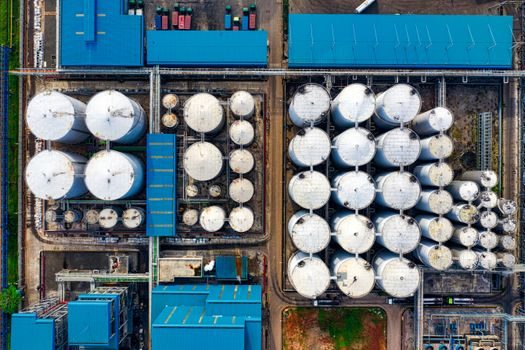
MAWP for a standard chemical tank container is around 4.0 bar with a test pressure of 6.0 bar; higher-pressure variants used for LPG, chlorine and similar products run at 17.7–22 bar MAWP per the IMDG T-code schedule [S3]. The T-code assigned under the IMDG Dangerous Goods List (T1 lowest pressure/temperature capability, T75 highest) is the master switch that determines what the container is legally allowed to carry — for example, T11 covers a wide range of hazardous liquids at 4 bar MAWP, T50 is the dedicated liquefied-gas code, and T75 is reserved for very low-temperature cryogenic service down to −196 °C [S3].
For buyers, the rule is: the product's UN number drives the T-code requirement, and the T-code drives the minimum relief-valve setting, MAWP and shell thickness — never the other way around. A datasheet that does not show the T-code and the matching relief valve set pressure (typically 110% of MAWP) is incomplete and should be returned for revision before any chemical is loaded [S2][S3].
Fittings, Top/Bottom Discharge and PRV Schedule
A chemical unit uses top-discharge only with a top manway (DN 500), a top fill/vent line, and a bottom-outlet ball valve that is piped through a drip tray but remains inside the frame envelope [S2]. A food-grade unit, by contrast, uses bottom-discharge: a DN 50 or DN 80 butterfly or ball valve at the lowest point of the barrel, piped through the side of the frame so the vessel fully drains under gravity — essential for CIP cleaning and for products that cannot tolerate dead legs [S3].
The standard fitting set that must appear on every datasheet: manway (DN 500, top), top wash nozzle, pressure/vacuum relief valve (set ≈110% MAWP, vacuum ≈−0.2 bar), rupture disc or secondary relief, thermometer pocket, sample valve, and the bottom valve schedule (DN 50 butterfly + DN 80 ball as the typical two-valve cascade) [S2][S3]. Material of the wetted parts (EPDM, FKM/Viton, PTFE seats) is just as critical as the barrel spec — wrong seal material on a 316L tank is the most frequent field failure I have seen.
Tare, Payload and the Lightweight-Trim Trend
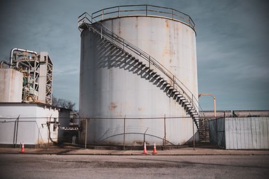
Standard stainless 20-ft tank tare sits in a 3,500–3,900 kg band, leaving a payload envelope of 26,000–30,400 kg when paired with a 30,000–34,000 kg MGW [S1][S2]. Since 2024, lightweight-trim builds using thinner heads, optimised baffling and aluminium walkways have pushed tare down toward 3,200–3,400 kg — a 200–300 kg reduction that translates directly into an extra 200–300 kg payload per trip, which compounds across a fleet running 80–120 trips per year per unit [S1].
If you are sizing a new fleet, ask the manufacturer for a tare-vs-payload sensitivity table at three different MGW bands (30, 32, 34 tonnes) before locking the design code — it costs nothing at datasheet stage and saves a six-figure retrofit later. For operators who already own older stock, calibration and periodic test intervals for ISO 20-ft units are the next thing to read once the spec is locked.
How to Read a Manufacturer Datasheet in 60 Seconds
Use this checklist against any datasheet you are handed: (1) design code + U-stamp or π-mark number; (2) material grade per shell and head; (3) capacity in litres and payload in kg at stated MGW; (4) MAWP and test pressure, with relief-valve set pressure; (5) IMDG T-code; (6) lining material and cure method if any; (7) fitting schedule including manway size, top/bottom valve arrangement, and seal materials; (8) ACEP plate next-inspection due date [S2][S3]. A datasheet missing any one of these eight lines is not a datasheet — it is a sales sheet, and the difference will be paid for in port delays or rejected loads.
Cross-check the datasheet against the physical ACEP plate and the tank's nameplate at survey, because a spec mismatch on capacity, MAWP or T-code is the most common discrepancy that surfaces during a periodic inspection. If a supplier cannot produce an as-built datasheet with all eight lines plus the original pressure-test certificate, walk away — the absence of that paperwork is almost always a leading indicator of undocumented repairs or unauthorised re-rating.
Standards and Certification Stack Behind the Sheet
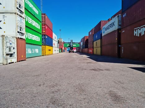
The full certification stack on a compliant 20-ft chemical tank container reads: ISO 1496/3 (frame), CSC or ACEP (sea approval), design code (ASME VIII-1, EN 14025 or CODAP), IMDG T-code (dangerous goods), TPED 2010/35/EU (if classed as transportable pressure equipment for gases), ADR/ADN for European road and inland-waterway haulage, RID for rail, and AAR M-1002 / M-1003 for North American rail interchange [S2][S3]. For food-grade units, EHEDG cleanability design and FDA/EC 1935-compliant seal materials add another layer.
For a deeper dive into barrel mechanics and how an IBC tank compares on capacity and handling, the trade-off is roughly: IBC sits at 800–1,250 L in a palletised footprint with no pressure rating, while a 20-ft ISO tank sits at ~26,000 L with 4-bar MAWP — about 20× the volume per unit and a very different chassis-and-trailer equation. Cleaning regime, by contrast, is a separate discipline entirely; for that, the tank cleaning machine reference covers nozzle pressures, cycle times and CIP validation — none of which appear on the build datasheet but all of which govern whether a unit is actually fit for the next load.
Two signals to track over the next reporting cycle: first, ISO/TC 104 SC3 is reviewing pressure-relief sizing assumptions for higher-density products (≥1.6 SG) — any change will move the standard relief set-pressure line on the datasheet. Second, the lightweight-trim build share is climbing on the chemical side as fleets chase payload; expect manufacturer datasheets to show tare in the 3,200 kg band as the new default rather than the historic 3,500 kg line [S1].