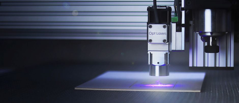
A modern industrial laser cutting machine is the integration of a high-power laser source, a fiber or mirror-based beam-delivery path, a CNC motion stage, a focusing cutting head, assist-gas circuitry, a chiller loop and a fume extraction unit [S1]. GWEIKE states cumulative shipments of its 10 kW-class fiber laser cutting machines have exceeded 2,600 units [S2], which is a useful proxy for the scale at which the high-power fiber sub-assembly is now a serial-manufactured commodity rather than a one-off build.
The dominant build path is sheet-metal fabrication of the machine frame and gantry, followed by subsystem integration: laser source, motion rack, cutting head, chiller, gas panel and electrical cabinet are assembled, then the optical path is aligned and beam mode, power and spot are calibrated [S4]. AccTek's product split — fiber, CO2 and mixed laser cutting machines in the same catalogue [S3] — shows how the same assembly line absorbs different source technologies, while process overview for cutting machine covers how these laser variants compare to plasma and waterjet on the shop floor.
Source technology: CO2 vs fiber (Nd:YAG/disc) and the wavelength split
CO2 lasers emit at 10.7 µm, which cannot be transported through optical fibre, so CO2 cutting machines use a mirror-based flying-optics path and stay mostly on ferrous sheet, 2D or 3D [S1]. Solid-state sources — Nd:YAG, fibre or disc — emit at 1.05–1.07 µm, which travels through fibre and couples well into aluminium, titanium and nickel alloys, which is why these are the sources behind robotic and automated 3D cutting cells [S1].
CO2 units of equivalent power are typically cheaper per watt than solid-state units but lose on flexibility, fibre delivery and non-ferrous absorption [S1]. The practical consequence on the build floor is that CO2 cutting machines need a sealed mirror gallery with three or more kinematic mounts, while fibre machines only need a fibre connector, a collimator and a focusing head [S1][S4]. The riser-cutting machine reference page documents how the same beam-delivery logic is adapted for tube and profile work, where the head moves in additional axes.
Beam path, cutting head and focus geometry
Whatever the source, the beam is focused through a lens system into a spot typically under 0.2 mm in diameter, producing a focal energy density on the order of 1.4×10¹⁰ W/m² [S1]. Assist gas is injected coaxially with the beam through the same nozzle: close-to-100% oxygen for ferrous stock (exothermic reaction, can roughly double cutting speed versus nitrogen and allows thicker plate) and inert nitrogen, argon or helium at pressures up to 20 bar for stainless, aluminium and other non-ferrous alloys [S1].
The flying-optics path is still the standard layout on gantry-style flat-bed cutters: three mirrors route the beam from the source across the moving gantry down to the z-axis cutting head, with the head carrying the focusing lens and the nozzle [S5]. The additive manufacturing material encyclopedia page is the natural cross-reference for shops that pair a cutting cell with a powder-bed or DED system, since beam-quality and assist-gas logic carry over directly.
CNC motion, worktable and Z-axis head
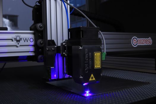
The cutting head is fixed to a z-axis that controls stand-off and focal-point position, while x/y motion is generated by a gantry or by a moving worktable; this is the subsystem that turns a beam into a kerf [S5]. GWEIKE lists 0–45° plate-bevel cutting heads and three-dimensional five-axis heads as standard product options on its fibre platform, meaning the z-axis is no longer a pure lift but a two-tilt biaxial head driven by servo or torque-motor pairs [S2].
On the drive side, the same gantry that carries the head also carries mirror 2 in a flying-optics CO2 system, so the motion envelope and the beam envelope are designed together [S5]. The multifunction process calibrator page is relevant where the cell is wired into a higher-level QA loop, since field calibrators are the tools typically used to verify the head's standoff and the focal offset after commissioning.
Assist gas, cooling water and fume extraction
Three utilities feed every cutting machine: a gas source (cylinder bank or bulk O2/N2 with pressure regulation up to 20 bar), a closed-loop chiller sized to the laser's kW heat load, and a fume extractor matched to the cutting area volume [S1][S5]. The gas panel typically combines high-pressure non-ferrous lines and low-pressure oxygen lines with regulators, solenoid valves and a nozzle-pressure sensor feeding back to the CNC.
For high-power fibre systems, the chiller is dual-circuit — deionised water for the source and tap or glycol water for the optics — and a chiller failure will stop the laser within seconds, which is why chiller status is hard-wired into the machine's interlock chain [S1][S4]. AccTek bundles pre-sales, installation and commissioning as separate service lines on its laser equipment, which is the industry norm because the chiller, gas and exhaust commissioning is where most warranty claims originate [S3].
Build flow on the shop floor
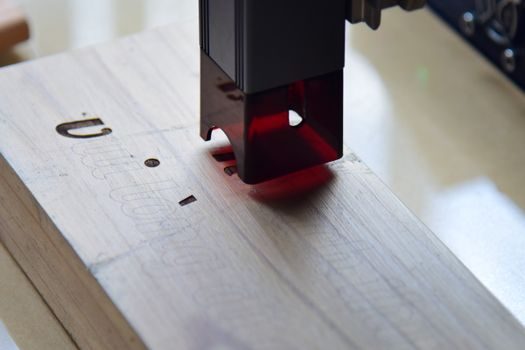
CTHS Laser's published build sequence for laser welding machines reads identically for cutting machines: cabinet production, then incoming inspection of the laser head, incoming test of the laser source, wiring and assembly of the optical head, cleaning head, control system and chiller, then beam calibration and spot-mode debugging after final installation [S4]. GWEIKE's documented supply chain — sheet-metal fabrication capacity, scientific assembly lines and a service network covering 180+ countries — is the scaled-up version of that sequence, with the assembly line laid out as moving-line stations rather than fixed benches [S2].
For shops cross-shopping different cells, V-process line covers a competing non-laser forming technology that is often benchmarked against laser cutting on thick plate, and the laser level entry covers the alignment tooling that shows up at the beam-calibration station of every fibre-laser assembly line [S1][S4].
Selection map: which source for which job
The decision matrix on the shop floor is short. CO2 wins on cost-per-watt and on thick ferrous plate, fibre wins on non-ferrous absorption, fibre delivery and integration into robotic or 3D cells, and CO2 still owns the non-metal cutting of acrylic, wood, fabric and leather where its 10.7 µm wavelength is preferentially absorbed [S1][S2]. GWEIKE's catalogue splits its product centre explicitly along that line — GH fibre machines for sheet metal and tube, separate CO2 machines for non-metal work [S2] — which is a clean specifier's rule: choose by the dominant material, not by the wattage.
For a working price reference across the whole laser family, the fiber laser welder price map covers the same wattage brackets and the same 2026 sourcing reality that cutting-machine buyers face. Adjacent selection guides worth scanning before signing a PO are the aluminum extrusion profile selection guide for shops cutting 6061/6063 profiles, and the ball screw manufacturing process reference for anyone auditing the motion subsystem inside the gantry.
The next verifiable node to watch is the rollout of 30 kW+ fibre cutting machines on thick stainless and structural steel, where assist-gas economics — not raw laser power — are now the throughput bottleneck; the second signal is the migration of five-axis bevel heads from welding prep into standard cutting-machine catalogues, which GWEIKE has already productised in 2024 [S2].