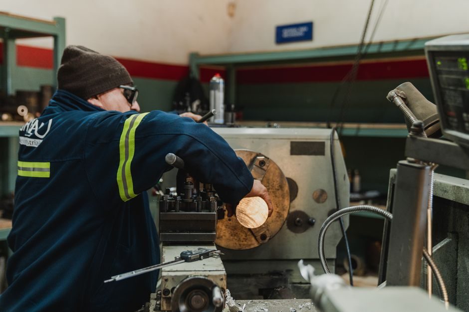
A CNC controller — also called a Machine Control Unit (MCU) — is a digital control subsystem that ingests G-code and M-code, runs real-time motion interpolation, and outputs drive commands to spindle and axis motors, typically holding workpiece tolerances near ±0.005 in. on standard 3-axis milling and turning work [S7].
Industrial CNC controllers in current production are dominated by four vendors — FANUC, Siemens, Mitsubishi Electric, and Delta — and their control units are deployed across precision machining, automotive powertrain lines, and aerospace structural-part cells [S2]. The FANUC 30i/31i/32i/35i-B series alone ships as PROFINET I/O Controller Safety Function options with ordering codes such as A02B-0323-R981, A02B-0326-R981, and A02B-0333-R981, confirming a consistent safety-bus interface across the 30i-B through PM i-A families [S3].
Two architecture families: PC-based vs PLC-based controllers
PC-based CNC controllers run motion software on industrial PCs (often real-time OS or soft-PLC cores) and are specified for high-axis-count mills, 5-axis machining centres, and complex multi-channel cells where the operator interface, post-processor, and network stack benefit from x86 processing headroom [S2].
PLC-based CNC controllers use hardened programmable logic controllers as the motion brain; they are favoured on lathes, basic 3-axis mills, and dedicated production-line machines running one part number for long campaigns where stability and mean-time-between-failure dominate over flexibility [S2]. Both families converge on the same downstream hardware — servo drives, spindle amplifiers, and absolute or incremental encoders — and both implement the G-code interpreter, tool-length compensation, and look-ahead trajectory planner that define the controller's machining behaviour [S6].
G-code loop: program intake to closed-loop axis motion
Industrial-grade CNC work runs on closed-loop control, where each axis servo is fed back by an encoder and the controller continuously trims the position error against the commanded trajectory [S5].
The control cycle in production CNC hardware is a four-step sequence: (1) program intake — load the G-code file generated manually or by CAM software, or stream it via manual data input (MDI); (2) interpretation — the controller parses G-codes for motion type and M-codes for spindle, coolant, and tool-change functions; (3) interpolation and acceleration planning — the trajectory planner issues position setpoints at the servo loop rate (commonly 1–4 kHz on mainstream controllers); (4) drive output and feedback — servo amplifiers move the axes, encoders return position, and the controller closes the loop [S2][S6]. Adaptive feed optimization, thermal error compensation, and predictive maintenance features layer on top of this loop on current-generation controllers [S2].
Hardware stack: HMI, CPU board, I/O, and safety bus
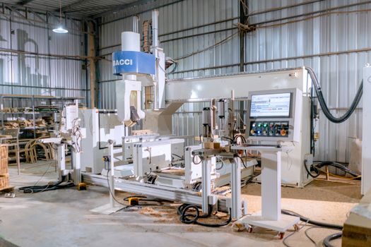
Field inputs and outputs terminate on the controller's I/O board and travel upstream to the main CPU through PROFINET, EtherCAT, or SERCOS on the most widely deployed platforms [S3][S2].
The FANUC 30i-B through 35i-B and PM i-A product lines expose PROFINET I/O Controller Safety Function connectivity with the dedicated option codes A02B-0323-R981 (30i-B), A02B-0326-R981 (31i-B5), A02B-0327-R981 (31i-B), A02B-0328-R981 (32i-B), A02B-0333-R981 (35i-B), and A02B-0334-R981 (PM i-A), each carrying a Safety Function license tied to the same PROFINET stack [S3]. This means a plant engineer can wire a single safety bus — e-stop, guard interlock, light curtain — into the controller's PROFINET I/O controller and the safety logic executes on the same CPU, removing a separate safety PLC. PC-based controllers with a motion controller front-end can also publish non-safety I/O over the same bus for drives and remote I/O panels. For higher-level temperature stability inside the control cabinet — critical because servo amplifiers and HMI panels drift in closed-loop accuracy with enclosure heat — a temperature controller is typically specified on the cabinet's cooling loop.
Comparison: PC-based vs PLC-based vs hybrid
Three practical axes separate the families for a process engineer: control flexibility, environmental tolerance, and integration depth. [S1]
On flexibility, PC-based controllers lead — they accept third-party post-processors, run CAM-side simulation, and pair with the broadest set of drives; PLC-based controllers trail on flexibility but lead on stability in dirty, hot, or high-vibration cells. On environmental tolerance, PLC-based controllers typically use fanless sealed enclosures rated for shop-floor particulates and 0–55 °C operation, while PC-based systems often need a conditioned cabinet. On integration depth, both families now expose PROFINET and EtherCAT I/O, so a plant network sees them as functionally similar nodes [S2][S3]. Where a line needs both, a PID controller loop is usually overlaid at the spindle or feed-rate level for process stability, decoupled from the CNC's geometric loop. For plants pushing more axes into the same cell, a multifunction process calibrator remains a common bench tool to commission and verify the analog channels feeding the controller from fixturing and probing.
Manufacturing workflow upstream and downstream of the controller
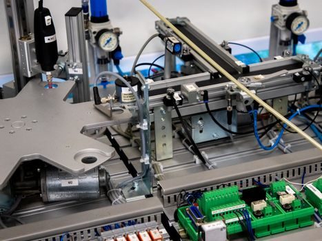
The controller sits in the middle of a digital thread: CAD model → CAM software → G-code post-processor → controller → drives → machine tool → in-process measurement → quality control [S7].
Upstream, a CAM package writes the G-code/M-code and the post-processor tailors it to the controller's dialect (FANUC, Siemens, Mitsubishi, Delta all have slightly different M-code and macro conventions). On the shop floor, the controller receives either the G-code file via network or MDI, then drives spindle speed, feed rate, and tool changes in real time [S2][S6]. Downstream of the cut, finished parts are measured with coordinate measuring machines, and advanced cells feed in-process sensors and machine vision back into the controller so deviations can be caught mid-run rather than at final inspection [S5]. Plants that run high-mix/low-volume work in this loop often compare their CNC cell's automation stack to other precision motion-bearing equipment, and the closest mechanical analogue is the closed-loop staging discussed in ball-screw smart manufacturing: precision grades, closed-loop stages, automation, where the same encoder-feedback logic the CNC controller applies to axes is applied to the screw itself.
Failure modes and engineering constraints
The dominant failure modes on a CNC controller are servo following error (encoder feedback loss or loop tuning drift), I/O bus dropouts (PROFINET/EtherCAT cable or node failure), and HMI panel degradation from heat and backlight wear on continuous-shift lines [S2][S3].
Closed-loop accuracy is contingent on the encoder resolution and the controller's servo loop period; a 17-bit absolute encoder running at a 1 ms loop gives roughly 20 arc-seconds of electrical resolution per axis, which sets the floor on achievable part tolerance. Open-loop stepper systems still exist on light-duty routers and 3D printers, but they cannot hold the ±0.005 in. band that defines industrial CNC work over long production runs [S5][S7]. Electrical noise on the shop floor — variable-frequency drives, welding inverters, large contactors — couples into analog encoder lines and degrades the loop; shielded cable, proper grounding, and physical separation from VFD power conductors are the standard countermeasures. When a machine builder specifies a controller, they weigh these failure modes against the application: high-end mills and aerospace cells get PC-based controllers with full closed-loop feedback, while production lathes and plasma tables often use PLC-based controllers with simpler diagnostics but longer mean-time-between-failure in harsh cells. Plants scaling these cells into fully automated lines often borrow the integration playbook used in RV reducer smart manufacturing: 2026 automation stack and quality gates, where the same PROFINET-driven safety and I/O topology is wired around a precision drivetrain instead of a spindle.
Trackable signals to watch through the rest of 2026: FANUC's 30i-B and 35i-B PROFINET safety function deliveries (option codes A02B-0323-R981 through A02B-0334-R981) and any Siemens Sinumerik ONE / Mitsubishi M800W revision notes that change the safety-bus topology, since both touch the same plant-side I/O map the FANUC stack currently defines [S3]. Buyers specifying new cells should also benchmark the ball screw manufacturing process their machine builder uses, because the screw's grade and preload set the mechanical floor under whatever the controller's loop can achieve.