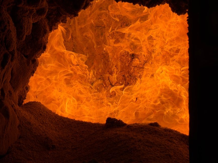
Line-frequency (mains-frequency) induction furnaces operate directly on 50 Hz or 60 Hz utility power, with the molten-metal bath itself acting as the single-turn secondary of a step-down transformer whose primary is the water-cooled copper coil that surrounds the refractory-lined crucible [S6].
Common furnace-body capacities in current China-sourced builds run from 1 t to 30 t per furnace, and foundries typically pair two or three identical bodies so that one is melting, one is holding/slaving, and one is being patched — the classic duplex or triplex mains-frequency arrangement for cast iron [S4][S5].
Foundations, Mass Loading and Building Envelope
For a 10 t cast-iron line-frequency body, the unfilled furnace mass runs roughly 18–22 t and the molten-metal load adds another ~12 t, so the foundation block is typically sized for an equivalent static load of 30–35 t plus a 1.5× dynamic factor for tilting cycles [S4].
The platform is normally a reinforced-concrete pad 400–600 mm thick, isolated from the main building slab by a 30–50 mm cork or rubber vibration break, because mains-frequency operation radiates strong 50/60 Hz hum that couples into adjacent structures if the pad is monolithic with the foundry floor. The tilting pit, when the furnace is hydraulic-tilt pour, must reserve a swing arc of 90°–95° and a hydraulic-cylinder pit depth of 1.2–1.8 m for a 5–10 t unit.
Water-Cooled Copper Coil and Cooling Plant
The induction coil is fabricated from heavy-wall rectangular or D-section copper tube (typical section 20 × 10 mm to 30 × 15 mm, wall 3–5 mm) wound in 18–28 turns depending on furnace voltage, and the entire coil is brazed or silver-soldered into a closed water jacket that carries the entire fault current and the bulk of the I²R heat [S6].
Cooling water demand is usually sized at 25–40 L/min per megawatt of installed furnace power, with a closed-loop chiller set to 35–40 °C supply and a return limit of 55 °C; conductivity must be held below 50 µS/cm to keep leakage currents in the coil-to-melt loop from spiking above 5–10 A, which would otherwise eat the coil wall at the water-outlet hot leg. Differential pressure across the coil should stay above 2 bar at full pump head, and a sudden drop below 1 bar is the classic early warning of internal scale blockage that will burn a turn within hours.
Capacitor Bank, Busbars and Power Supply Sizing
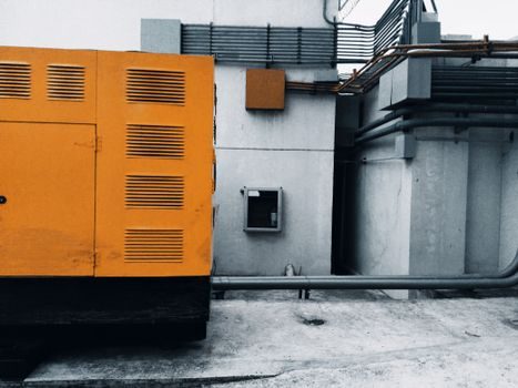
Because the air-gap between coil and melt is large, a line-frequency furnace is a poor-cosφ load (cosφ typically 0.15–0.25 cold, 0.30–0.40 hot), and a switched capacitor bank rated for 8,000–12,000 kvar per 10 t body is mounted as close to the coil terminals as physically possible to hold bus-bar reactance down [S6].
Voltage at the coil terminals is held in the 700–1500 V band, stepped down from the 10 kV or 35 kV shop feeder through a furnace transformer with on-load tap changing (±5 % steps over 17–19 taps is typical) so the input can be trimmed as the melt height rises and the load impedance changes. Harmonic distortion is mostly 5th and 7th from the rectifier side, and IEEE 519 current-TDD limits are the usual contract clause if the furnace is tied to a shared plant bus; for a dedicated feeder the limit is set by the utility interconnect agreement.
Refractory Lining, Sizing and Dry-Out
Standard practice is dry-vibrated silica-alumina for cast iron (acid service, 1500–1600 °C class) and magnesia or alumina-magnesia spinel for steel and high-Mn iron, rammed in 8–12 lifts with intermediate pneumatic compaction. Typical lining thickness is 110–150 mm in the sidewall and 180–250 mm in the bottom for a 5–10 t body; total ramming mass runs 1.5–3.0 t per furnace.
Dry-out follows a controlled 36–72 hour ramp from cold to 1100 °C, holding 200 °C and 600 °C dwells to drive off free and combined water, then a sinter soak at 1200–1300 °C to lock the grain structure before the first metal is charged. Skipping the 600 °C dwell is the single most common cause of early lining failure — water trapped in the bond migrates to the hot face and pops a 200–400 mm spall within the first 20 heats.
Installation Sequence, Acceptance Tests and When to Stop
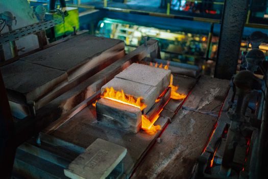
The clean sequence used on 2025–2026 China-built installs is: pit and foundation cure (≥28 d) → coil and yoke assembly on the shop floor → hydraulic tilt rig alignment (±0.5°/m levelling) → capacitor bank and busbar landing → transformer tap check → control cabinet cold test → water system flush at 1.5× working pressure for 30 min → refractory ram and cure → first metal charge no earlier than 72 h after final ramming [S4][S5].
Acceptance on first cold-water test: coil-to-ground insulation ≥ 100 MΩ at 1 kV, cooling loop pressure drop within ±10 % of design, and capacitor contactor self-hold verified across all tap steps. Acceptance on first melt: power-on ramp to 50 % within 4 h, full power within 8 h, and bath temperature at 1450 ± 20 °C for cast iron before the first pour. If coil-to-ground insulation reads below 10 MΩ, do not energise — the moisture is still in the lining and the first strike will punch a hole through the coil. If the lining spalls more than 5 % of its surface area in the first 30 heats, the dry-out profile was wrong and the lining must be replaced rather than patched, because patch repairs rarely survive more than 100 heats on a mains-frequency body.
Standards, Sourcing Footprint and Common Failure Modes
The equipment is traded internationally under China customs HS-code subheadings for industrial electric furnaces and parts of structures of iron or steel, with general tariff rate 30–35 % and MFN 4–10 % depending on the exact subheading, which is what a buyer's customs broker will pull against for a turnkey line [S3].
Mainstream factory documentation typically references generic national standards for industrial induction melting installations and IEC-style safety and EMC clauses; buyers should confirm the exact GB, IEC, IEEE and any utility-specific clauses (IEEE 519 for harmonics, IEC 60076 for the transformer, IEC 61936-1 for the power installation) before signing the FAT protocol. Cross-check the related installation discipline for adjacent equipment such as crossed-roller guides on the tilting trunnion and the linear guide rails on the electrode or stirrer carriage — both are common wear points when a mains-frequency furnace is mis-aligned, and the same goes for the VFD cabinet if the hydraulic-tilt pump and the vibratory feeder on the pour line share the same bus.
Three recurring failure modes in 2024–2026 field reports: (1) coil burnout at the water-outlet hot leg from scale build-up, (2) lining pop-outs from a skipped 600 °C dry-out dwell, and (3) capacitor-can rupture from busbar reactance when the bank is mounted more than 8 m from the coil. All three are caught by routine infrared thermography of the coil outlets (any leg running >8 °C above its peers is failing), annual lining thickness gauging at four reference points, and a clamp-on power-quality log on the furnace feeder at first commissioning. For a broader look at how the mains-frequency body fits into a complete foundry melting line and where it sits against medium-frequency units in the overall furnace family, those reference pages map the decision tree.
If a project is in the bidding stage in July 2026, the two trackable signals to watch are the tap-changer delivery lead time (currently 14–20 weeks on 10 MVA furnace transformers) and the water-chiller lead time (8–14 weeks for a 400–600 kW closed-loop skid), both of which set the realistic erection window once the foundation has cured.
For related coverage, see E-axle supply shortage & risk map 2026: SiC, magnets, interfaces.