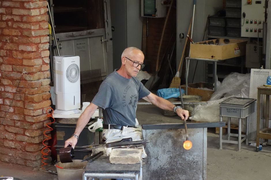
Selection of a line frequency induction furnace — a mains-frequency (50/60 Hz) coreless or channel-type electric induction unit that couples directly to the grid without an intermediate frequency converter — is governed by melt mass, alloy chemistry and electrical infrastructure, not by kilowatt rating alone.
The technology sits at the bottom of the frequency ladder: medium-frequency (MF) units run typically 1–10 kHz via solid-state converters, and high-frequency (HF) units run tens of kHz to MHz [S3]. Line-frequency (LF) units keep the mains frequency, which drives a distinct set of selection gates: melt mass per heat, alloy class, refractory wear, power factor, and harmonic mitigation. For foundries pouring grey iron, ductile iron or large carbon-steel heats, the core induction-furnace physics of electromagnetic stirring and joule heating apply; the question is which furnace class fits the pour schedule.
Melt mass and alloy class — the first gate
LF coreless furnaces are commonly deployed above ~3 t per unit and up to 60 t or more in iron foundries, where the larger coil diameter at 50/60 Hz still couples acceptable energy into the bath [S1]. Below ~1–2 t, the coil becomes physically inefficient at line frequency, and the buyer is pushed toward medium-frequency coreless or push-up channel designs [S3]. The selection rule of thumb that process engineers use is: pick LF when the required melt rate (t/h) and the tap mass both exceed the practical MF envelope, and when the alloy is ferrous (grey iron, ductile iron, carbon steel, low-alloy steel). LF channel furnaces (also called "core" or "submerged-arc channel" units) are typically specified as holding or duplexing vessels downstream of a primary coreless melter, and are sensitive to a minimum bath level — running a channel furnace dry destroys the channel refractory in minutes.
Refractory lining and chemistry compatibility
Lining selection is the second gate and the single largest maintenance cost line in an LF install. For grey and ductile iron, the workhorse is a silica-based ramming mix with boron oxide flux; for steel heats, the lining moves to high-alumina or magnesia-spinel with stricter installation density. The slower bath turbulence at 50/60 Hz (compared to MF) reduces refractory erosion in ductile iron where FeO/SiO₂ slag attack is the dominant wear mode. Selection must lock: (a) ramming mix grade, (b) minimum sinter temperature before first iron pour, (c) target campaign life in heats or weeks, and (d) lining patch-versus-full-rebuild interval. A foundry that fails to lock the lining spec at the RFQ stage will discover the cost differential only after the first 6 months of operation. [S1]
Electrical infrastructure and power factor
LF furnaces draw heavily distorted, low-power-factor current from the grid; a 20 t, 12 MW LF coreless unit can pull apparent power at 0.7 power factor or worse, and inject characteristic 5th, 7th, 11th and 13th harmonics back into the feeder. Selection must address: (a) dedicated MV feeder with adequate short-circuit MVA at the PCC, (b) switched or tuned capacitor banks sized for kVAr compensation at the furnace transformer secondary, (c) harmonic filters or active front-end drives if the local utility enforces IEEE 519 compliance, and (d) furnace transformer impedance (%Z) matched to the coil to limit inrush. A medium-frequency supply removes the LF harmonic problem entirely but introduces the converter cost and the cooling-water burden [S3].
Melting rate, kWh per ton and duty cycle
LF coreless furnaces typically deliver 350–600 kWh per ton of liquid iron delivered to the pouring ladle, depending on charge makeup, tapping temperature and holding practice. The selection lever is the matching of tap mass, charge cycle time, and shift demand. A foundry pouring 8 t every 90 minutes has a different optimal furnace size and count than a foundry pouring 8 t every 4 hours; the first is a one-furnace high-utilization case, the second is a two-furnace flexibility case where one unit idles or holds. For a broader cost frame across frequency classes, see the Induction Furnace 2026 Price & Cost Guide: Capacity, Frequency and Coil Tier Levers cost analysis. [S2]
Comparison: LF coreless vs LF channel vs MF coreless
Three options compete for the same pour schedule: (1) LF coreless, (2) LF channel holding/duplex, and (3) MF coreless with solid-state converter. On tap mass, LF coreless and LF channel both scale above ~3 t efficiently; MF coreless dominates below 2 t. On melt rate per installed MW, MF coreless leads at smaller tap sizes because of higher power density, but LF coreless wins on a $/ton basis at large tap sizes because the frequency converter is eliminated. On refractory life, LF channel holds 24/7 with care, while LF coreless campaigns are batch-tied. On harmonic burden, LF coreless is the worst offender, MF coreless with active front-end is the cleanest. The selection cut is therefore: choose LF coreless when tap mass and melt rate dominate and the utility allows harmonics; choose MF coreless when tap mass is small, when the alloy is non-ferrous, or when harmonic limits are tight; choose LF channel only as a holder or duplex unit, never as a primary cold-melt vessel. For the broader furnace-class decision frame, the Induction Furnace Selection: 5 Gates That Lock the Furnace Class Before RFQ piece covers the upstream class gating. [S3]
Who LF is for — and who it is not for
LF coreless is FOR: grey-iron and ductile-iron foundries above ~3 t per heat; carbon-steel melt shops with large ladle metallurgy; copper-alloy melters in some specialty cases; operations with robust MV feeders and on-site harmonic mitigation. LF coreless is NOT for: non-ferrous melts where MF's stirring and power density are needed; small job-shop foundries below ~2 t per heat; sites with weak utility feeders (low short-circuit MVA) that cannot absorb the inrush; or operations with strict IEEE 519 limits and no budget for harmonic filters. Channel furnaces are NOT for: cold start-up service, batch operation with long idle periods, or any duty where the bath level can drop below the channel throat. [S1]
Operational limits and failure modes to spec against
The dominant failure modes on an LF install are: (a) refractory campaign end with a runaway hearth — often flagged by a rising cold-coil temperature or by a drop in power-factor during the last 5–10% of campaign; (b) water-cooled coil leak into the bath — a catastrophic event; (c) harmonic-induced capacitor-bank failure if PF compensation is mis-sized; (d) furnace transformer overheating from harmonic currents that derate the unit below nameplate kW; (e) stirring velocity too low for alloy homogeneity, particularly for high-carbon Fe melts where slag-metal reaction depends on bath movement. The RFQ must lock the trip-and-alarm map, the cold-coil temperature trip, the water-flow interlock, and the lining-wear-tracking log. A good process engineer will also lock the spare-coil lead time (often 8–14 weeks for large LF coils) before signing the purchase order, not after. [S2]
Sourcing, standards and documentation to request
The technical annex to the RFQ should reference: furnace transformer impedance and harmonic spectrum, IEEE 519 compliance evidence at the PCC, refractory installation procedure and sinter schedule, lining-wear monitoring method, water-cooling circuit schematic with interlock list, spare-parts list with lead times, and a documented cold-coil temperature vs power curve. For the broader foundry process where the LF unit feeds a moulding line, the molding line interface (pouring temperature, ladle transfer time) must be sized to the LF tap. Standards naming to be careful with: do not pin specific limits to specific clauses unless the OEM has confirmed the exact edition in writing. [S3]
Next verification node: request the OEM's harmonic-study report tied to your specific PCC short-circuit MVA, and the refractory supplier's campaign-life warranty expressed in heats or tonnes, not as a generic number. Two trackable signals to watch for on incoming bids: (1) a single-line diagram showing MV switchgear, furnace transformer impedance (%Z), PF capacitor bank and harmonic filter as one coordinated package; (2) a lining-wear monitoring plan with a defined end-of-campaign trip value, not a verbal "inspect monthly" line.