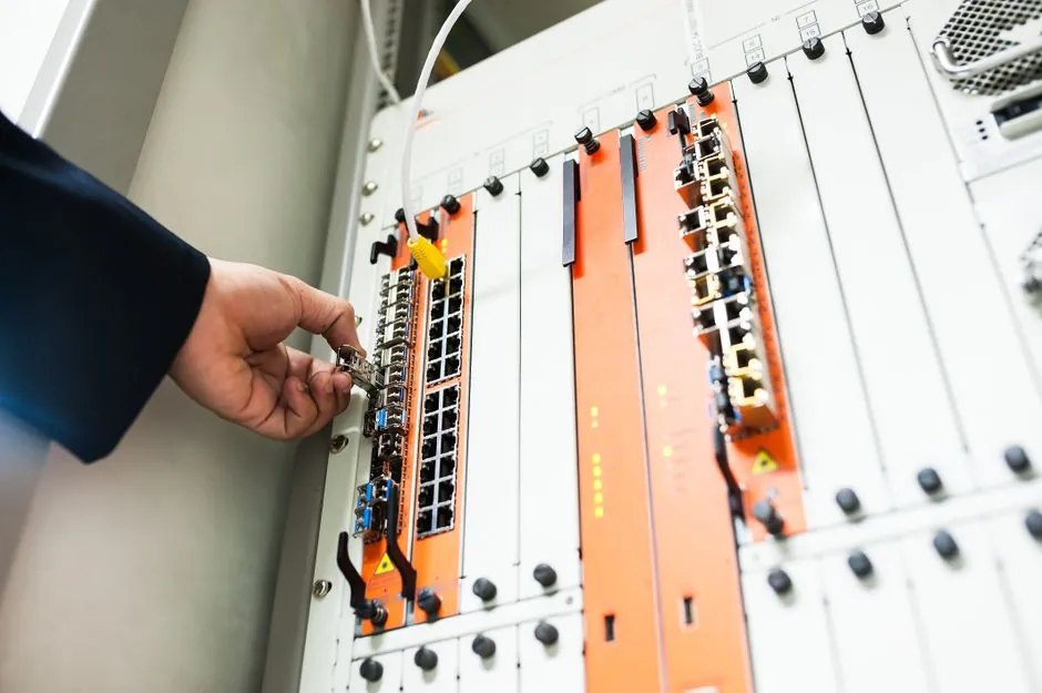
Telecom enclosure buyers who need draft-free internal cavities, integrated heat-sink bosses, and 50-5,000-piece annual volumes are specifying lost foam casting lines built around four coupled spec gates: EPS pattern density 18-25 kg/m³, refractory coating dry film 0.8-1.5 mm, flask vacuum 0.04-0.07 MPa, and 80-150 moulds per shift on the automatic molding line feeding the pour station [S3][S7].
The enclosure market spans two material families that map cleanly onto EPC: ductile and grey iron for outdoor cabinet bases and ground bars (pour temperatures around 1350-1400 °C), and aluminum alloys A356/A380 for indoor radio-unit and edge-server housings (pour around 700-720 °C) [S3][S9]. The four spec gates govern the casting the same way for both, but the foam and coating windows narrow as the alloy gets hotter.
Pattern Foam Density Window for Enclosure Foam Patterns
EPS pre-expansion density is the first spec cut, and the published EPC band for telecom-grade iron and aluminum patterns is 18-25 kg/m³, with ferrous work sitting at the 22-25 kg/m³ end and thin-wall aluminum at 20-25 kg/m³ to limit residue formation at lower pour temperature [S3][S7].
Below 16 kg/m³ the bead collapses unevenly under coating weight and tears during flask fill, producing surface rippling that propagates straight into the as-cast skin; above 25 kg/m³ the pattern resists decomposition and leaves carbonaceous defect clusters in the casting, so suppliers cap commercial EPS at 22-25 kg/m³ for iron and steel grades and add 0.05-0.1% calcium stearate as an anti-collapse additive to the pre-expansion [S3]. For enclosure foam patterns, which carry large flat faces and several internal bosses, the practical target is 20-22 kg/m³ for aluminum and 22-24 kg/m³ for ductile iron.
Coating Refractoriness and Dry-Film Permeability
Refractory coating performance is governed by dry-film thickness (0.8-1.5 mm) and gas permeability, with commercial water-based zircon or mullite coatings rated for grey and ductile iron up to about 1400 °C pour and alumina or magnesia-enriched grades required above 1600 °C for austenitic stainless and high-manganese steel [S3].
Dry coating permeability is typically specified in the 0.5-2.0 cm⁴/(g·min) band, because a coating that is too dense traps pattern pyrolysis gas and re-introduces veining no matter how hard the vacuum is pulled under the flask [S3]. For telecom enclosure work, the common spec is a zircon-based coating at 1.0-1.2 mm dry film for ductile iron bases and a mullite grade at 0.8-1.0 mm for aluminum housings, both applied by dipping rather than flow coating to keep the dry film uniform around internal rib intersections.
Flask Vacuum and Sand-Loop Sealing
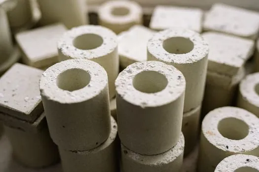
Negative-pressure sealing under the flask is the third spec gate, and a capable EPC cell holds 0.05-0.07 MPa absolute throughout fill and skin formation; the published drop-out threshold is 0.04 MPa, below which pattern vapour cannot be evacuated fast enough and the metal front breaks through the coating [S3][S7].
The mechanical side is a flask flatness spec of ≤1 mm/m on the molding line feeding the station, because any warping in the flasket breaks the vacuum seal and propagates collapse folds straight into the casting [S3]. Sand compaction in blind mould areas is specified at ≥85% dry-sand density to prevent pattern collapse during pour, a figure ZHY Casting ties directly to defect rate in iron castings [S2]. For telecom enclosure work, with castings that often exceed 600 mm in one dimension, the practical approach is a vibration-compaction table plus a top sand-fill hopper and a dedicated vacuum reservoir sized to hold 0.05-0.06 MPa for at least 90 seconds after pour.
Throughput and Mould-Loop Sizing for 50-5,000-Piece Annual Volumes
Throughput is the spec that converts the process into cost per enclosure: a manual single-station cell runs 10-20 moulds per shift, while a fully automated line with robot dipping, flask indexing, and shake-out reaches 80-150 moulds per shift, which is the real driver of per-piece cost in the 50-5,000-piece annual band that EPC serves [S3].
Shake-out and cooling capacity must be matched to pour weight, because an under-sized cooling leg lengthens cycle time and an over-sized one wastes floor space; the published 2026 buying-guide figure for a 100-mould/shift cell is roughly 4-6 workers per shift with one pouring operator, one moulding operator, and a shake-out/finishing crew [S3]. For telecom enclosure buyers, the deployment pattern that consistently works is a single automated line sized at 80-120 moulds/shift feeding one line-frequency furnace at 1-3 t/h melt rate, which absorbs mid-volume enclosure programs without the capex of a high-pressure die cell [S7].
Material and Defect Considerations Specific to Enclosure Geometries
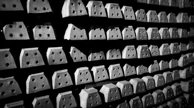
Ductile iron enclosure bases are the dominant outdoor cabinet casting, and the gating recommendation is bottom or side gating to cut carbon defect rates in thick sections, with vertical or inclined pouring preferred over horizontal upward pouring to reduce residue accumulation on upward-facing machined faces [S2].
The published effect is a 30%+ drop in carbon defect rate when pouring position is moved from horizontal upward to vertical or inclined on iron castings, which matters for enclosure bases that are machined flat for gasket sealing [S2]. For aluminum A356 enclosure housings, the typical recommendation is bottom or stepped gating to manage oxidation in thin walls, with the published 2026 spec window calling for foam density at 20-25 kg/m³ and a mullite coating at 0.8-1.0 mm dry film [S2][S3].
Selection Comparison: EPC vs Die Casting vs Sand for Enclosures
Across the four decision criteria that matter for telecom enclosures, EPC sits between high-pressure die casting and conventional sand casting: tool cost is lower than die casting because EPS patterns replace hardened steel dies, but per-piece cycle time is longer, so the economic sweet spot is the 50-5,000-piece annual band [S1][S3].
On geometry, EPC delivers draft-free internal cavities and integrated mounting bosses that sand casting can only reach with multiple cores, but cannot match die casting's sub-0.3 mm dimensional tolerance on small features; on alloy range, EPC covers aluminum, grey and ductile iron, and stainless steel, while die casting is effectively limited to aluminum and magnesium; on tooling lead time, EPS patterns are weeks, steel dies are months [S1][S9]. For telecom buyers, EPC is the right call when the part is complex, the lot is mid-volume, and the alloy is castable in an open EPS-moulded flask.
Trackable 2026 Signals for Enclosure EPC Sourcing
Two signals worth monitoring before the next sourcing round: the 2026 buying-guide band for commercial EPS density sits at 18-22 kg/m³ for ferrous castings and 20-25 kg/m³ for non-ferrous, with 22-25 kg/m³ as the anti-collapse cap when calcium stearate is dosed at 0.05-0.1% in pre-expansion [S3].
The 2026 published vacuum envelope is 0.04-0.07 MPa under the flask, and a related sourcing article on AAC block selection for data center shells tracks the same spec-driven approach for the building envelope that surrounds telecom cabinets, which is worth cross-referencing when an enclosure program is part of a wider data-center build. Buyers specifying new EPC cells for enclosure programs should anchor the RFQ on the four spec gates above and verify flask flatness, dry-film permeability, and vacuum hold time in the FAT, rather than on quoted moulds-per-shift alone.