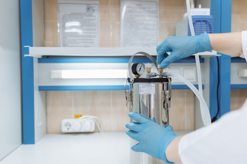
An industrial measuring instrument leaves the factory floor only after a chain of 10 to 15 discrete operations — sensor element build, signal-conditioning PCB assembly, welding/sealing, firmware load, and multi-point calibration — each gated by documented work instructions under an ISO 9001 quality plan [S1].
The two reference factories surveyed in mid-2026 — Precision Sensors & Systems (established 2000, process weighing, level, flow, temperature, metal detection) [S1] and Mikrometry (Shenzhen-based, hand-held force, torque, coating-thickness, hardness and height gauges) [S2] — show the same skeleton: incoming-component inspection, sub-assembly, final assembly, calibration against traceable standards, and burn-in or soak test before pack-out.
Process Skeleton: BPMN View of an Instrument Build
A 2018 Springer process-modelling study formalised the same flow on a thermocouple-probe line using BPMN 2.0, decomposing each instrument into operations with explicit precedence, BOM, and bill-of-material-operations (BOMO) data sets [S3]. That model — process chart + BOM + BOMO feeding a BPMN diagram — remains the canonical reference for how a measuring-instrument factory sequences its 10-plus operations: incoming parts, sensor-element processing, PCB population, soldering, welding, cleaning, firmware flash, calibration, housing close, final test [S3].
On a real process-instrument line that skeleton maps to: loadcell/strain-gauge bonding, ultrasonic or radar level probe head assembly, signal-trim board stuffing, PLC and SCADA integration, then chamber calibration against a dead-weight tester or reference RTD [S1]. A 25-year-old Korean manufacturing-process-chart standard (KSA 3002) defined the original graphical symbol set, but BPMN has since replaced it because it adds execution, monitoring, and re-design steps the older notation could not represent [S3].
Sub-Assemblies and Sensor-Element Fabrication
Precision Sensors' product list — loadcells, ultrasonic and radar level probes, temperature sensors and instrumentation, PLC and SCADA stacks, plus Pepperl+Fuchs distributed I/O [S1] — maps one-to-one onto discrete sub-assembly cells, each with its own fixturing: loadcell bonding jigs with creep-correction software, radar-probe horn welding fixtures, and temperature-probe sheath swaging tools. Mikrometry's catalogue shows the hand-held-instrument analogue: digital force gauges, torque testers (including bottle-cap torque), coating-thickness gauges operating on both magnetic and eddy-current principles, Leeb and Shore hardness testers, digital height gauges and portable microscopes, each a separate assembly cell [S2].
Calibration is not a single step but a recurring gate. Coating-thickness gauges, for example, are verified on coated reference standards before pack-out and re-checked against magnetic-principle and eddy-current-principle reference foils in the field [S2]. Leeb hardness testers require impact-body geometry verification and a reference test block (typically HLD ≈ 800 ± 6) before shipment, and Shore hardness testers run on Shore-A and Shore-D durometer verification stands with controlled indentor force [S2].
Electronics, Firmware, and Signal Conditioning
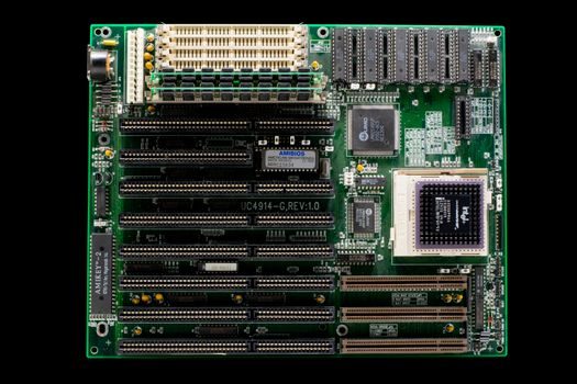
Every electronic measuring instrument in the surveyed factories carries a signal-conditioning PCB — loadcell amplifiers for weighing, ultrasonic/RADAR time-of-flight front-ends for level, strain-gauge bridges for force, magnetic and eddy-current pickup coils for coating thickness, and impact-body velocity sensors for Leeb hardness [S1][S2]. The board population step uses SMT lines with reflow profiles typically constrained to 235–245 °C peak for lead-free SAC305 solder, followed by selective wave or hand soldering for through-hole connectors and gland terminations.
Process automation is treated as a deliverable, not an accessory: Precision Sensors lists P&ID procurement, PLC and SCADA integration, plus channel-partner support for Precision Transducers loadcells as part of its build scope, and Pepperl+Fuchs distributed I/O is wired in for hazardous-area and fieldbus segments [S1]. A broader view of plant-floor automation, including PLC/SCADA stack selection and sourcing, is covered in the abrasives smart-manufacturing automation map for 2026, which lines up the same control architecture on a different process line.
Calibration, Traceability, and Final Test
Calibration is the gating step that turns an assembly into a measuring instrument. Force gauges are verified against a load cell traceable to a national force standard, torque testers against a reference torque arm, coating-thickness gauges against certified coated foils of known thickness, and Leeb hardness testers against HLD/HLD+15 reference blocks [S2]. On the process-instrument side, weighing systems are trimmed against dead-weight or hydraulic force calibration, level instruments against a known column height, and temperature instruments against a reference RTD or dry-block calibrator in a stirred liquid or block bath [S1].
Final test is structured: a burn-in of typically 1–4 hours at elevated ambient (commonly 40 °C to 50 °C) screens infant-mortality component failures, followed by a functional sweep across the measurement range. Documentation per unit typically includes calibration certificate, traceability statement to national standards (NPL, NIST, NIM, KRISS equivalents), and a conformity declaration to the relevant IEC or ISO instrumentation standard where the instrument is sold into regulated process plants.
Enclosure, IP Rating, and Hazardous-Area Integration

For process instruments the enclosure step is a process-control gate, not a packaging step. Precision Sensors specifies fully-welded, high-resolution, lightweight bodies for its level and flow probes, with material and welding-procedure choices driven by the service fluid and pressure rating [S1]. Mikrometry's hand-held instruments are typically IP54-rated ABS or aluminium bodies with rubber overmoulds, and their Shore-durometer indentor geometry and Leeb impact-body mass are mechanical calibrated features, not options [S2].
Plants that need inline flow measurement, weighing, level and pressure readback into a control system often pair these instruments with complementary items such as a pressure transmitter for closed-loop pressure control, and they may run dimensional checks with a vision measuring machine or contour measuring machine on machined components. Selection of the right sensing technology is governed by the process medium and the required accuracy class; a process-engineer overview is provided in the encyclopedia entry on pressure transmitters.
Quality System, Documentation, and Standards Anchors
ISO 9001 is the baseline quality system in both reference factories, with documented work-instruction routing, non-conformance handling, and calibration recall procedures [S1][S2]. Specific instrument standards are layered on top: ISO 376 for force calibration, ISO 868 for Shore hardness, ASTM E114 for ultrasonic thickness, and the relevant IEC 61508 / SIL clauses where the instrument sits in a safety loop [S1][S2].
Process-instrument factories additionally maintain hazardous-area certifications (ATEX, IECEx, UL/CSA Class I Div 1 or Div 2) on welding, cable gland, and potting operations, and they run calibration recall cycles of 6 or 12 months depending on the instrument class [S1]. For buyers, the operational signal to track is a vendor's documented calibration interval, the traceable reference standard cited on each certificate, and the lot-level traceability of sensor elements — a platform-scale selection guide for 2026 shows how those same checks are written into a weighing-instrument RFQ for one specific instrument class.
Trackable signals for the next sourcing cycle: instrument vendors that publish open calibration certificates with stated measurement uncertainty (k=2), disclose sub-assembly sources for sensor elements, and ship units with a documented preventive-calibration interval rather than a generic 12-month sticker.