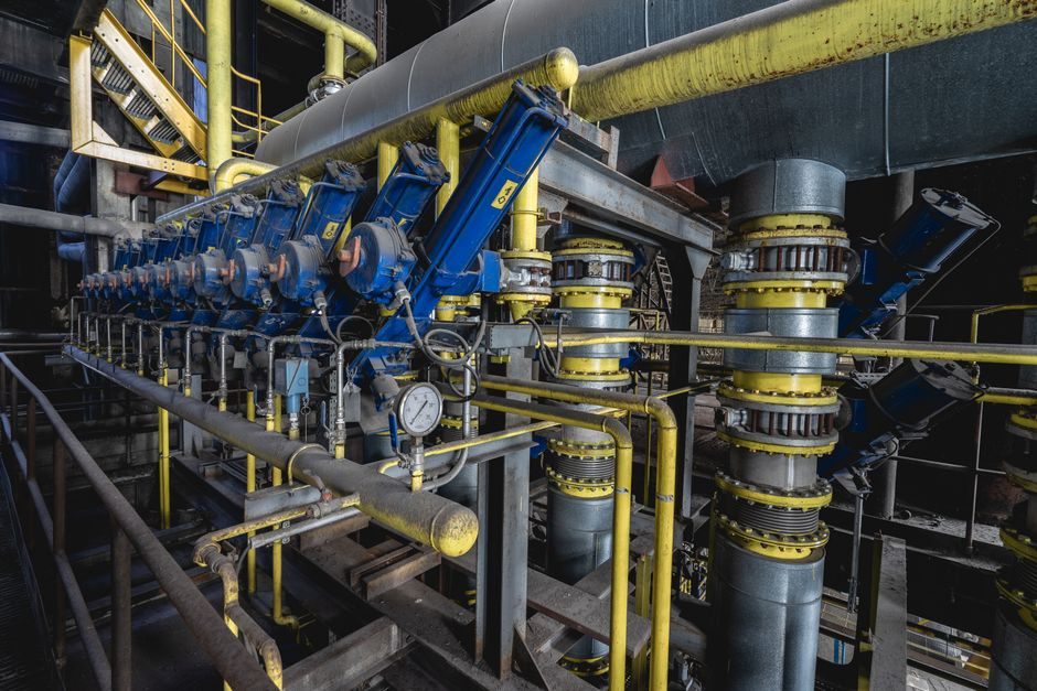
A multistage pump earns its place on a P&ID the moment system head climbs past the point where a single-stage end-suction or centrifugal pump becomes physically or economically unreasonable — in practice, beyond roughly 60-80 m, or whenever boiler-feed, RO-boost, or high-rise booster service pushes the duty into the 100-500 m head band [S1][S6].
Each stage typically adds 15-40 m of head at a given flow, so a 5-stage build hits 150-200 m and a 10-stage build 300-400 m, and the casing pressure the pump has to contain rises with it — that is why horizontal multistage frames are commonly rated to 100 bar while vertical builds are usually limited to 45 bar [S6].
Where Multistage Pumps Beat Single-Stage Units
Head per stage is the trigger. Field data from the 2026 Changyu sizing guide put the application envelope at 10-1000 GPM (≈ 2.2-227 m³/h) and 50-400 m, with boiler feed, RO pressure boost, high-rise boosting, and industrial transfer as the four dominant duties [S1]. The same source recommends a 1-2 m margin between NPSH available and NPSH required, which is the single most violated rule on hot-water and condensate service [S1].
The trade-off is axial thrust accumulation across stages, which is why every multistage build includes either a balancing drum, balancing disk, or opposed-impeller arrangement [S2].
Horizontal vs Vertical: Decision Criteria
Horizontal multistage frames are the default for high head. They reach up to 1000 m (100 bar) and flows up to 1200 m³/h, with a long-coupled design and a dedicated thrust bearing that takes the accumulated rotor load [S6]. Vertical multistage units, often canned or semi-canned, stop at about 450 m (45 bar) and 500 m³/h because the suction-stack geometry leaves no room for a thrust bearing — the stages are hydraulically balanced instead [S6].
Use the matrix below for quick pre-selection before you open a vendor curve:
Selection criteria — Horizontal vs Vertical multistage:
- Head ceiling: Horizontal up to 1000 m / 100 bar; Vertical up to 450 m / 45 bar [S6].
- Flow ceiling: Horizontal up to 1200 m³/h; Vertical up to 500 m³/h [S6].
- Thrust handling: Horizontal uses external thrust bearing; Vertical relies on stage-by-stage balance [S6].
- Footprint: Vertical is a tall, small-plan, in-line unit; Horizontal needs coupled baseplate and alignment [S2].
- Service fit: Vertical dominates RO, light industry, and compact skid builds; Horizontal dominates boiler feed, power, and large industrial transfer [S1].
For duties inside the 50-150 m, 50-500 GPM window — typical RO pressure boost — the vertical stainless build is the most common spec, and VFD-readiness (U/f curve, minimum 4:1 turndown, IE3 motor) should be written into the data sheet at RFQ stage [S1].
Material and Seal Class by Fluid
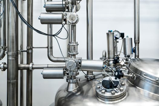
Standard builds cover boiler feed, water transfer, and clean service with cast iron (FC) casings and stainless shafts. Corrosive or hygienic service shifts the spec to 316L stainless wet-end components, as in the SPX Waukesha Cherry-Burrell Multistage 200 Series, which is 3-A sanitary, rated to 86 bar (1250 psi) casing pressure and 17 bar (250 psi) differential, with 316L wetted parts and a water-flush double mechanical seal as standard [S7].
Aqueous chemical and seawater transfer usually calls for SCS cast stainless or the YST special stainless offered on the Yokota MCF/MCH range (40-200 mm bores, 50-400 m head, 0.1-7 m³/min) [S2]. For abrasive slurry or solids-bearing transfer, the same Changyu table that maps head and flow also flags abrasion-resistant impeller materials and harder seal-face pairings as a line item, not an option [S1]. The pump selection and sizing reference (Walther/Kern-style curves reproduced in the [S3] engineering PDF) shows minimum-flow lines for single-suction impellers climbing from about 30% of BEP at Nss 6000 to 80-90% at Nss 13000-14000, which is why suction-specific speed is the gate you check before locking stage count [S3].
Standards That Bind the Spec
Three standards cover most multistage pump RFQs. ANSI dimensional standards (ANSI B73.1 for chemical end-suction, plus the multistage equivalents) guarantee interchangeability between manufacturers when spare-parts logistics matter [S4]. API 610 governs petroleum, chemical, and gas-industry service, with stricter nozzle-load, bearing-L10, and seal-plan requirements that materially raise cost — only specify it where the duty truly demands it [S4]. 3-A sanitary standards cover food, dairy, and beverage multistage builds such as the SPX 200-Series, where cleanability and CIP compatibility are non-negotiable [S7].
For a sizing PDF that shows the model-code breakdown (CDL/CDLF/CDLK with stage counts 1-200, bore families from 1 to 200 m³/h, and kW per stage), the Changyu 2026 catalogue is the most complete single reference for vertical stainless builds [S1]. For horizontal heavy-duty ranges, manufacturer selection tables follow the same convention: pump type, stage count, suction/discharge bore in cm, then a head classification suffix [S2].
Sizing Procedure That Actually Works
Lock four numbers first, in this order: required flow at the duty point (not the average), required head at the duty point (including all static and friction losses at design flow, not at some future turndown), available NPSH at the worst-case liquid level and temperature, and the continuous service temperature that drives seal and material choice [S1][S3]. Then read the manufacturer's family curve and pick a stage count that puts the duty point inside the ±10% BEP band — running a multistage pump at 50% of BEP is a guaranteed bearing-temperature and recirculation problem on single-suction impellers above Nss 10000 [S3].
Add a 1-2 m NPSH margin, write the casing pressure rating (it scales with stage count and head), and specify mechanical seal flush — Plan 52/53A for clean water, Plan 11 for hot boiler feed, quench for hazardous fluids [S1][S7]. For RO and high-rise service, default to VFD-rated windings, IE3 or IE4 efficiency, and a 4-20 mA + HART or IO-Link driven speed reference so the pump can be trimmed at commissioning and not at six months of operating pain [S1].
Who Should Not Pick a Multistage Pump
Three cases kill a multistage spec on day one. First, viscous service above 200-300 cSt — the affinity laws and the BEP map both drift, and a positive-displacement gear pump or diaphragm pump will outperform it on efficiency and on NPSH [S1][S3]. Second, very low head below 30-40 m — a single-stage end-suction or self-priming unit is cheaper to buy, align, and maintain. Third, highly pulsating flow or high solid content — a multistage impeller will not tolerate either, no matter how hard the material spec is pushed [S1].
For wet-end cleaning chemicals, low-flow CIP transfer, or semiconductor slurry, a plunger pump typically dominates the spec sheet — a different family with a different selection logic altogether. Likewise, when the duty is feed to an RO bank with tight pressure turndown, a vertical multistage with a VFD still beats a horizontal frame on footprint, but only if the suction piping is genuinely flooded and NPSHa is documented in writing before purchase order [S1].
Shortlist Logic and Trackable Signals
Once the four lock-numbers above are in the datasheet, the shortlist is mechanical: 2-3 vendors whose published curves bracket the duty point from below and above at the right stage count, with a casing pressure rating that meets 1.1× shut-off head plus 10% surge margin, and whose material offering matches the fluid-and-temperature pair [S1][S2][S7]. API 610 is added only when the process unit is refinery, gas-plant, or large-scale chemical with documented nozzle-load and MTBF expectations [S4]. 3-A is added only for hygienic service; ANSI dimensional interchangeability is added only when the spares strategy assumes drop-in replacement [S4][S7].
Trackable signals to watch: revised API 610 and 3-A editions when published, VFD harmonic and IE5 motor efficiency updates from major OEMs, and a continued push by Chinese and Korean vertical-multistage manufacturers into the 200-500 m³/h, 200-400 m head band that was previously horizontal-only territory [S1][S2][S6].
Background reading: Confined Space Oxygen Detector: 4-Gas Spec Map and Selection Gates.