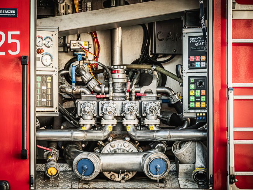
Industrial plunger pumps operate across 100–10,000 PSI (6.9–689 BAR) and 0.13–240 GPM (0.49–908 LPM), with available fluid-end metallurgies spanning brass, nickel aluminum bronze, 304 SS, 316 SS, and duplex stainless steel [S4]. The category sits inside the broader plunger pump family of positive-displacement machines, distinct from rotary designs like a gear pump or a diaphragm pump because pressure is built by linear reciprocation of a solid plunger in a precision cylinder, not by rotating or flexing elements.
For process engineering, the practical pressure envelope runs from 70 bar at the low end up to 2,070 bar (1,000–30,000 psi) in waterjet and ultra-high-pressure cleaning duty, with reciprocating hydraulic pump variants using the same kinematics [S5]. The decision is rarely about whether a plunger pump can do the job; almost any high-pressure pump in a process plant uses this mechanism. The decision is about configuration, metallurgy, and standards compliance, which are the variables that drive reliability.
Pressure Class, Flow, and Multiplex Configuration
Triplex (3 plungers, 120° crank phasing) and quintuplex (5 plungers, 72° phasing) are the workhorse configurations in oil & gas, waterflood, RO, and high-pressure cleaning, with model families such as 101T-4, 133T, 163Q, 217Q, and 250T-5 representing field-proven frame sizes [S3].
Capacity scales with plunger area and stroke: theoretical displacement per revolution is V_disp = (π/4) × D² × s, and theoretical flow is Q = V_disp × N, where D is plunger diameter, s is stroke, and N is the running speed [S1]. In sanitary and food-grade builds, single-stage high-pressure plunger units from SPX FLOW's Gerstenberg Schröder line cover 115–30,000 L/h, with motor enclosures limiting noise to below 76 dB at full power — a useful benchmark when a pump is being placed near operators or a control room [S2]. Selection tip: do not oversize flow; if the calculated Q sits in the bottom third of a frame's published range, step down a frame size to keep volumetric efficiency above ~90% and to keep plunger velocity in the wear-friendly band.
Fluid-End Metallurgy and Plunger Materials
Fluid-end and plunger selection is a chemistry problem first, a pressure problem second. Standard offerings at one industrial OEM include brass, nickel aluminum bronze, 304 SS, 316 SS, and duplex stainless steel, paired with plungers in hardened steel, tungsten carbide, ceramic, or hard-Co coatings depending on the service [S3][S4]. For chloride-bearing brine and RO high-pressure service, 316 SS or duplex is the conservative minimum; for acidizing and HCl-based well-stimulation fluids, elastomer compatibility and alloy resistance to pitting and SCC must be checked against the specific stimulation chemistry, not against a generic "stainless" label.
Plunger surface treatment is a separate decision from fluid-end body material. Hard-Co, tungsten carbide, and ceramic plungers address abrasion in slurry pipeline, descaling, and mining service; coated plungers extend packing life and let the operator push packing-tightening intervals out by multiples [S3]. For sanitary and hygienic service, 316L fluid-end wetted parts with surface finishes matched to the cleaning regime (typically Ra ≤ 0.8 μm for CIP) are the baseline, and that is where sanitary plunger pumps overlap with metering pump hygiene requirements [S2].
Standards Compliance: API 674, API 675, and ASME BPVC

Three standards define the floor of any industrial plunger-pump spec. API 674 covers positive-displacement reciprocating pumps and governs design, materials, pulsation control, vibration limits, testing, and documentation — the standard to call out for oil & gas, pipeline, and waterflood duty [S1]. API 675 governs controlled-volume (metering) positive-displacement pumps, with explicit accuracy, repeatability, and control-response requirements; this is the right standard when the pump is feeding chemical-injection or precision-dosing skids.
ISO 16330 sits alongside API 674 for performance testing, safety, and technical specifications, and is typically referenced in EU and Middle Eastern tenders. The fluid end itself is a pressure vessel under ASME BPVC Section VIII, so the wetted side must meet the same design, weld, and test rules as a comparable pressure vessel [S1]. When the duty is sanitary or food-grade, layer in 3-A, EHEDG, or the regional equivalent on top of the metallurgy and surface-finish spec, since those certifications are the ones the customer's QA team will audit, not API 674.
Driver, Pulsation Control, and Mechanical Interface
Driver choice follows the available utility and the mobility requirement. Electric motor, gas/diesel engine, hydraulic, and pneumatic drives are all standard across the major plunger-pump lines [S4]. For fixed installation in a hazardous area, electric motor with a VFD or soft starter is the default; for mobile well-servicing and stimulation units, diesel via a planetary gearbox or belt drive is the norm; for remote skids, hydraulic drive from an existing centrifugal pump-driven power unit or from a dedicated hydraulic power pack is common.
Pulsation control is not optional above ~100 bar. Reciprocating pumps generate pressure pulsations at multiples of running speed, and those pulsations drive piping vibration, valve-seat erosion, and instrument noise. API 674 sets vibration and pulsation limits that the supplier must demonstrate by test, and a properly sized pulsation dampener (charged with nitrogen to a defined precharge, typically ~60–80% of discharge pressure) on the discharge manifold, plus a suction stabilizer on the inlet, is the standard engineered solution [S1][S3]. Rupture discs and relief valves must be sized to the discharge flange and located as close to the fluid end as practical, on the pump side of any discharge block valve — that placement rule is consistent across OEM installation manuals [S6].
Sealing, Packing, and Leak Detection

The packing is the consumable. Packing sets are available in multiple materials (PTPE, aramid, graphite, and specialty compounds), with lubricated packing arrangements and packing-leak-detection options that let the operator catch a packing failure before it becomes a containment breach [S3]. A non-lubricated packing runs cooler and is preferred for sanitary service, but the operator must accept a tighter replacement interval; lubricated packing with a separate lubricant injection runs longer between repacks and is the workhorse choice for continuous-duty oil & gas and waterflood.
For high-pressure waterjet and hydrostatic-test service, packing cooling water or a flush fluid is often piped to the packing gland to manage frictional heat; without it, packing life drops by a factor of three or more in continuous duty. The plunger itself, in most designs, does not contact the fluid — the packing handles the dynamic seal, and the plunger is a hard, wear-resistant consumable that can be replaced without machining work [S1]. That separation is one of the practical reasons plunger pumps dominate high-pressure and abrasive service over the alternative diaphragm pump approach, which has a fixed-life elastomer or PTFE diaphragm that limits pressure and temperature.
Selection Criteria: Triplex vs Quintuplex vs Simplex
The mainstream choice between simplex (1 plunger), triplex (3), and quintuplex (5) is a function of flow target, pulsation tolerance, and acceptable footprint. Simplex is acceptable for low-flow, intermittent, or test-stand duty where flow smoothness is irrelevant. [S1]
Quintuplex pushes theoretical flow smoothness above 95% and shifts residual pulsation to a higher frequency, which is easier to filter; the trade-off is larger crankcase, higher first cost, and more complex maintenance. For RO systems at 55–80 bar, triplex with a properly sized dampener is the workhorse; for waterjet cutting at 3,000–6,000 bar and for pipeline pumps at high horsepower, quintuplex is the standard answer [S1][S3]. On lower-pressure, lower-pulsation service, engineers sometimes evaluate a gear pump or a centrifugal pump instead, and the rule of thumb is: if required pressure is below ~16 bar and the fluid is clean and non-abrasive, a rotary or centrifugal design is usually cheaper to buy and to maintain.
Who Should NOT Pick a Plunger Pump

Plunger pumps are the wrong tool when the fluid cannot tolerate trace lubrication, when pulsation is unacceptable to downstream equipment, or when the duty is genuinely low-pressure. A diaphragm pump is the better fit for ultra-clean, sterile, or shear-sensitive fluids because the diaphragm isolates the fluid from the moving parts; a gear pump is the better fit for low-pressure, high-viscosity lubrication oil and resin service; a centrifugal pump is the better fit for very high flow at low head, where the reciprocating design's frame count and footprint become uneconomic. [S1]
Avoid plunger pumps where the budget cannot cover a real maintenance program. Continuous-duty plunger service demands periodic packing replacement, valve servicing, and crankcase oil analysis; if the operating team cannot commit to that, the reciprocating design will fail faster than a comparable rotary or centrifugal machine. For low-flow, high-pressure chemical injection, a plunger-based metering pump governed by API 675 is the correct variant; do not use a general-purpose API 674 process plunger pump for chemical injection where the controlled-volume accuracy specification of API 675 is the contract requirement [S1].
Shortlist Logic: A Five-Step Gate
Step one: confirm required differential pressure, flow, and fluid. If P × Q (hydraulic power) places the unit above ~50 kW and below ~2,000 bar, the plunger pump is in scope; if pressure is below ~16 bar, walk away. Step two: set the standard — API 674 for process and pipeline, API 675 for controlled-volume / metering, ISO 16330 for EU/Middle East tenders — and put those references on the data sheet before vendor talks start [S1]. Pick metallurgy and plunger surface from the fluid chemistry rather than catalog default, with available pump materials including brass, nickel aluminum bronze, 304 stainless steel, 316 stainless steel, and duplex stainless steel.
Step four: select multiplex configuration by flow target and pulsation tolerance — simplex for intermittent test, triplex for general industrial, quintuplex for high-horsepower continuous. Step five: confirm driver, instrumentation, and relief layout. The relief valve must be on the pump side of any discharge block valve, sized to the discharge flange, with a rupture disc upstream where the fluid is incompatible with a leaking relief seat [S6]. A shortlist that passes these five gates is one a QA team can audit against API 674 or ISO 16330 documentation deliverables without surprises.
Next verification nodes: pull the OEM installation, operation, and maintenance manual before purchase (NOV publishes a Multiplex Plunger Pumps Installation, Care, and Operation manual that codifies relief placement and rupture-disc sizing rules [S6]); and request a factory performance test at the duty point with a witnessed NPSH verification, since reciprocating-pump NPSH margin is sensitive to suction-line geometry in a way that rotary-pump calculations can hide. For broader procurement context, the vacuum-pump selection criteria guide uses a similar six-gate logic and is a useful cross-check on how fluid-handling specifications are structured across categories.