Offshore wind production is the integrated process of converting kinetic energy in marine air masses into grid-frequency electricity using three or four coupled subsystems: a horizontal-axis turbine with a step-up gearbox or direct-drive generator, a support structure selected for water depth, an inter-array and export cable network, and a SCADA/microgrid control layer that balances ramp rates against grid demand [S1][S2].
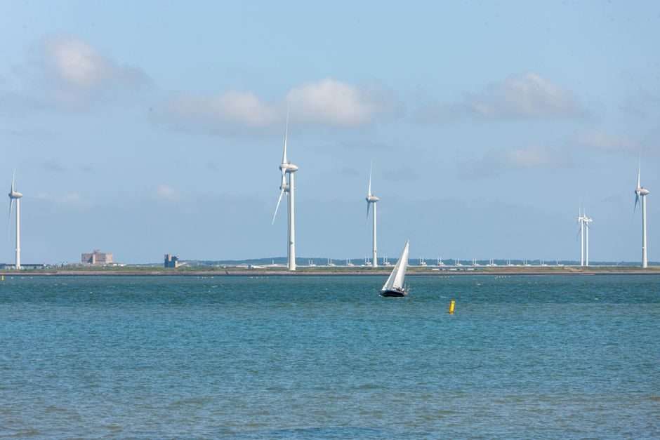
Commercial arrays range from 80-turbine, 288 MW fixed-bottom installations such as Butendiek in the German North Sea (80 × 3.6 MW units, commissioned mid-2015) [S4] to multi-gigawatt floating demonstrators now being project-financed by developers like Hexicon, whose semi-submersible TwinWind platform is designed for water depths well beyond the 50–60 m fixed-bottom ceiling [S2]. Scale, water depth, and grid distance are the three variables that drive every spec downstream.
Turbine Drivetrain: Geared, Direct-Drive and Hybrid Topologies
Rated unit capacity for offshore service has climbed from 3.6 MW at Butendiek (2015) into the 14–18 MW class by 2025–2026, with rotor diameters above 230 m; the trend is documented across developer filings and consortium briefs [S4][S5]. Three drivetrain architectures compete: (1) medium-speed geared permanent-magnet generators with a compact three-stage planetary/helical gearbox, (2) direct-drive multi-pole permanent-magnet synchronous generators eliminating the gearbox, and (3) rare-earth-free hybrids (synchronous reluctance or electrically excited rotor) being scaled to reduce NdFeB exposure.
Medium-speed geared units typically operate the gearbox input shaft at 5–10 rpm and the generator at 300–500 rpm, with planetary first stages carrying the highest torque density per stage; direct-drive generators run rotor tip speeds in the 80–90 m/s band, which forces larger airgap diameters and stricter blade-tip clearances. Blade pitch control and full-span variable-speed power conversion (IGBT back-to-back, grid-tie filter) are common to all three. For plant-level control, the same SCADA layer that governs the turbine also feeds a pressure transmitter stack monitoring hydraulic pitch and yaw systems — a 4–20 mA HART loop with HART-IP backhaul is still the default field-level signal inside the tower.
Foundations and Floating Platforms: When Steel Goes Underwater
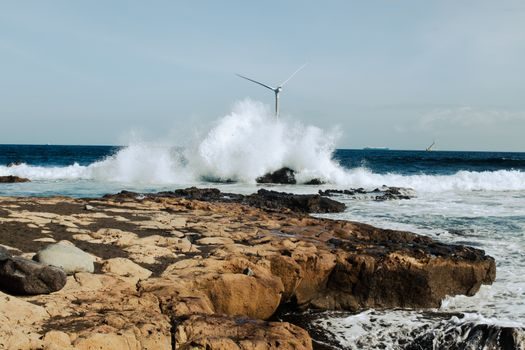
Foundation selection is governed by water depth, seabed geology, and fabrication yard throughput. Monopiles dominate depths to roughly 30–35 m and diameters up to 10 m; jackets (4-legged steel lattice) extend useful range to about 60 m; gravity-base structures (GBS) remain a niche where a competent seabed exists close to shore; floating platforms — semi-submersible, spar-buoy, or tension-leg — open the >60 m segment that is unavailable to fixed steel [S2][S6].
Steel grades for primary tubular members commonly follow EN 10025 grades S355 to S460 for monopiles and API 2W/2Y-equivalent for jacket bracing, with wall thicknesses in the 50–100 mm band; corrosion allowance in the splash zone is typically 6–10 mm extra wall, sometimes paired with cathodic protection by aluminium-indium sacrificial anodes. The Hexicon TwinWind concept uses a moored semi-submersible with a shared anchor base for two turbines, explicitly trading structural mass for cable-length savings at deep sites [S2]. Floating structures impose a new control loop — passive ballasting plus active blade-pitch thrust damping — that does not exist in monopile installations.
Subsea Cables: Inter-Array, Export and the Dynamic Cable Problem
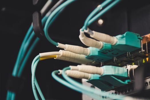
Subsea cabling is a process bottleneck that often gates commissioning. Three-conductor 33–66 kV XLPE-armoured inter-array strings collect groups of 6–12 turbines into an offshore substation, where a 132–275 kV XLPE HVAC export cable (or ±320 kV/±525 kV HVDC converter pair for long hauls) lands power at the onshore substation. Dynamic cables on floating units are a distinct sub-class: they use helical wire armours designed for fatigue cycles rather than the single-bend static installation of fixed-bottom cables. [S1]
J-tube and I-tube cable entry through the monopile transition piece, vertical-pendant hang-off on floating platforms, and pull-in winch tensions in the 30–80 t range are the typical installation variables. Cable failure remains one of the largest unplanned-loss categories in the operating fleet, and most operators now log flow meter data on forced cooling water in the export cable trench as part of the same SCADA archive.
Microgrid, Storage and Short-Term Coordination
Offshore wind farms behave as a weak-grid source: inertia is low, ramp rates can exceed 10 MW/s on gust fronts, and the upstream grid cannot absorb unsmoothed output. The hybrid energy-storage microgrid literature applied to offshore oil platforms in CNOOC's published work [S1] transfers directly: a battery (LiFePO<sub>4</sub> or LTO) sized in the 5–20 MW/5–20 MWh range pairs with supercapacitor or flywheel modules to absorb sub-second fluctuations, with a distributed coordinated controller riding above the turbine PPC (pitch/power converter) loop.
For oil-and-gas platform microgrids, the cited CNOOC study reports that distributed coordination of battery + supercapacitor hybrid storage shortens frequency deviation settling time by a measurable margin relative to a rule-based baseline, and the same hardware stack is being retrofitted into wind farm PPCs [S1]. Operators also use this control layer to manage industrial valve sequencing on the offshore substation's cooling and fire-water loops, where pneumatic actuator feedback is wired back into the same PLC.
Standards, Sourcing and the People Side
The relevant standards stack spans IEC 61400-1 (design requirements), IEC 61400-3-1 (fixed offshore) and IEC 61400-3-2 (floating), DNV-ST-0359 and DNV-ST-0119 for floating-mooring analyses, CIGRE TB 490 / 496 for subsea cables, and the IP54/IP55 nacelle ingress requirements for offshore salt-air duty. Plant-level control, including the SCADA gateway that aggregates turbine and substation telemetry, is the same PLC class used in onshore process plants. [S2]
Workforce and supply-chain constraints are now a co-equal risk to steel: a 15 GW/yr build rate requires 1,500+ trained offshore technicians and 200+ installation vessel-days per gigawatt in the European basin, per the industry data aggregated by [S3]. The U.S. National Offshore Wind R&D Consortium [S5] lists the workforce gap and Jones-Act vessel availability as funded R&D lines, and Hexicon's project pipeline [S2] makes floating-turbine serial production — not the turbine itself — the gating constraint. As mass production tech matures it follows the same learning-curve logic laid out in Battery Energy Storage Production: Cell Formats, Chemistry Trade-offs and Pack Assembly: throughput, not peak performance, is the variable to watch.
Trackable signals over the next two quarters: floating-pilot financial-investment-decision announcements from at least two European developers (Hexicon's pipeline [S2] is the public one to watch), the next DNV revision of the floating-turbine standard, and the first published capacity factors for any 15 MW+ unit operating through a full winter. Manufacturing cadence for monopile towers, rather than turbine nameplate rating, will be the practical bottleneck through 2027.