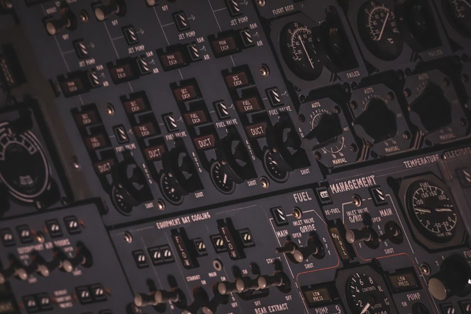
A PID controller is a three-term feedback device combining proportional (P), integral (I), and derivative (D) action on the error e(t) = setpoint − measurement, with the canonical output form u(t) = Kp·e(t) + Ki·∫e(t)dt + Kd·de(t)/dt [S4]. Selection begins with the plant: first-order lag time τ, dead time L, integrator presence, and actuator saturation bound — these four parameters decide whether a plain P, a PI, or a full PID is even appropriate [S2][S3].
The same source data backs the three practical levers an engineer tunes in 2026: control mode (P / PI / PD / PID / PI-D), anti-windup scheme (back-calculation, clamping, or external tracking), and tuning rule (Ziegler-Nichols, Ms-constrained, IAE/ISE-optimal, or model-predictive for time-delay systems) [S2][S3]. Skipping any one of these gates produces a controller that drifts, overshoots, or never settles — the failure modes that drive most field complaints.
Control Mode vs Plant Type: When PI Beats PID
PID is not always the right answer; PI alone covers the majority of flow, level, and temperature loops because the derivative term amplifies measurement noise and amplifies valve wear in slow processes [S4]. For processes dominated by dead time L (transport, batch, multi-stage heating), single-loop PID tuning formulas tuned to the peak of maximum sensitivity Ms are documented in process-control literature and suppress overshoot below 10–15% while keeping the loop robust at Ms = 1.4–2.0 [S3].
The selection rule of thumb grounded in standard texts: if the ratio L/τ < 0.1, P or PI is enough; if 0.1 < L/τ < 1.0, a full PID with derivative-on-measurement (not derivative-on-error) prevents derivative kick on setpoint changes; if L/τ > 1.0, a single PID loop is rarely enough and a cascade or Smith-predictor structure should replace it [S3]. For self-regulating processes the closed-loop time constant sits at roughly 1.5–3× the open-loop time constant τ, and the integral time Ti typically falls in the 0.5–5×τ band depending on tuning criterion.
Anti-Windup: Why It Is Non-Negotiable on Any Saturated Plant
Integral windup is the field failure that takes out the most PID loops: when the actuator saturates, the integrator keeps accumulating error, the controller output latches at the supply limit, and the loop takes many seconds to recover after the setpoint is reduced [S2]. A documented benchmark case shows a saturated first-order plant with actuator bound ±10 producing a controller output of 36.29 in steady state — over 3× the actuator range — when anti-windup is disabled, and a long recovery delay when the setpoint drops from 10 to 5 [S2].
Two anti-windup strategies are dominant in 2026 software stacks. Back-calculation feeds a tracking gain Kb (the inverse of the anti-windup time constant) from the difference between unsaturated and saturated controller output back into the integrator; clamping simply freezes the integrator when the output hits the actuator limit. Tracking mode is the third option for cascade architectures, where an external tracking signal — for example, the actual actuator output minus a feedforward term — is fed back to the PID block's tracking port, with gain Kt defining the recovery time constant [S2]. For an actuator feedforward gain of 1 on a plant with DC gain 1, the tracking signal must subtract the feedforward contribution to remain accurate, otherwise the integrator will still wind up by the feedforward magnitude.
Selection Criteria: A Four-Gate Scorecard
Engineers selecting a PID controller for a new loop should score candidates on four gates rather than reading brochures. Gate 1 — process fit: control mode matches plant type per the L/τ rule above, and derivative action is on the measurement (not error) for noisy or setpoint-aggressive loops. Gate 2 — anti-windup support: back-calculation, clamping, and external tracking are all configurable, not hard-coded; actuator bounds are user-settable in engineering units, not a fixed 0–100% scale. [S1]
Gate 3 — tuning toolkit: built-in autotuner supporting at least one of {Ziegler-Nichols, IAE-optimal, Ms-constrained}, plus relay-feedback identification for closed-loop tuning without open-loop step tests. Gate 4 — form factor and I/O: match the temperature controller form factor (1/16 DIN, 1/8 DIN, 1/4 DIN, rail-mount), the analog I/O count (1-loop, 2-loop, 4-loop), the comms protocol (4-20 mA + HART, IO-Link, EtherCAT, PROFINET, Modbus TCP), and the safety integrity level (SIL 1/2/3 per IEC 61508 for process safety, SIL 3 being the requirement for burner management and ESD loops).
Comparison: P, PI, PID, PI-D, Cascade
The five common control structures line up against four decision criteria — noise tolerance, setpoint-tracking speed, disturbance rejection, and complexity. P-only: highest noise tolerance, fastest setpoint response for proportional-only plants, weakest disturbance rejection (steady-state offset), and the simplest implementation. PI: medium noise tolerance, medium setpoint speed, strong disturbance rejection, moderate complexity — the workhorse for flow and level. PID: low noise tolerance (derivative amplifies noise), fast setpoint tracking, strong disturbance rejection, higher complexity — the standard for temperature and motion. [S2]
PI-D (derivative on measurement): medium noise tolerance, fast setpoint tracking without derivative kick, strong disturbance rejection, moderate complexity — preferred for cascade master loops. Cascade (primary PID + secondary PI inner loop): highest disturbance rejection when the inner loop captures the dominant disturbance, medium setpoint speed, highest complexity, and the right call for any loop where the actuator has its own slow dynamics (e.g. positioner with hysteresis, motion controller with backlash). For tuning, single PI/PID formulas tuned to the peak of maximum sensitivity Ms deliver enhanced disturbance rejection for time-delay processes, per published process-control work [S3].
Implementation Paths: Open-Source, Software Block, and Industrial Hardware
Three implementation paths coexist in 2026. Path one is open-source: a Java PIDController class in a public repository demonstrates the canonical 6-commit reference implementation with the three gains Kp, Ki, Kd exposed as class fields and a fixed-step update loop suitable for embedded or desktop deployment [S1]. The code level shows the algorithm: P-gain multiplication, integrator accumulation, and a finite-difference derivative, with the loop period hard-coded — a useful starting template but not a tuned industrial controller.
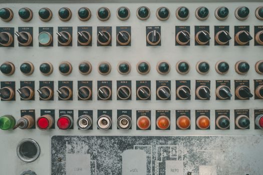
Path two is software-block, dominated by MATLAB/Simulink's PID Controller block which supports both back-calculation and clamping anti-windup as built-in methods, plus a tracking mode for cascade and feedforward configurations. The same block interfaces with the Simulink Control Design PID Tuner for one-click autotuning and exposes a documented saturation example with actuator bound [-10, 10] and a first-order plant with saturation time [S2]. Path three is industrial hardware: panel-mount PID controllers from vendors in the temperature controller and motion controller categories, with discrete 1/16 to 1/4 DIN form factors, HART or IO-Link comms, and SIL-rated firmware for safety instrumented functions. The vision controller class, often used for high-speed inspection, overlaps with PID only at the lighting intensity and conveyor speed control edges; full PID loops in vision systems usually sit on a separate motion or PLC rack.
Tuning Rules and Verification Signals
Three tuning rules cover most loops. Ziegler-Nichols (open-loop step test): fit the plant to a first-order-plus-dead-time model K·exp(−Ls)/(τs+1), then set Kp = 1.2·τ/(K·L), Ti = 2·L, Td = 0.5·L — fast setpoint response but 20–60% overshoot, so it is rarely the final answer for production. IAE/ISE-optimal: minimise the integral of absolute error or squared error using published lookup tables indexed by L/τ — gives 5–15% overshoot, preferred for batch and setpoint-tracking loops. Ms-constrained: limit the peak of the sensitivity function Ms = 1.4–2.0, giving robust loops that survive 30–50% gain variation — preferred for process loops where the model drifts, including most flow and level control [S3].
Three signals confirm a PID is correctly specified. The first is the closed-loop time constant sitting at 1.5–3× the open-loop τ — a slower loop is over-damped and wastes actuator bandwidth, a faster loop risks instability. The second is the sensitivity peak Ms measured from a closed-loop step test, ideally between 1.4 and 2.0 for robust operation. The third is the actuator activity — a healthy PID commands the actuator to move on 60–80% of sample intervals at steady state; under 30% indicates the loop is over-damped, over 90% indicates valve hunting and the Kp or Kd term is too aggressive.
Limitations: Where PID Stops Working
PID fails on three process classes and should be replaced rather than retuned. Strongly nonlinear plants (pH, dead-end filtration, exothermic batch reactors with gain varying 5–10×) need gain-scheduled PID or model-predictive control — a single Kp cannot cover the operating range. Pure integrating plants (level on a vessel with no self-regulation) need a PI with low gain and a long Ti plus a separate anti-reset windup strategy on the valve; a plain PID will integrate the error and saturate the valve. Long-dead-time plants (L/τ > 1.0) need a Smith predictor, a dead-time compensator, or a model-predictive controller — a single PID will limit the gain so heavily that disturbance rejection collapses. [S3]
A 2026 procurement check on a new PID loop should also flag: (a) the absence of bumpless transfer between manual and auto modes, which causes a bump equal to the integrator state on every operator handover; (b) derivative action on the error rather than the measurement, which causes a derivative spike on every setpoint change equal to Kd·Δsetpoint/Δt; (c) fixed integral action without external-reset capability, which blocks cascade and override control. All three are fixable in software but become warranty-and-recall items if locked into shipped firmware. A process engineer writing a 2026 spec should also keep the gas alarm controller and gas mass flow controller classes in mind, since their internal loops are tuned to different criteria (fast trip response, not setpoint tracking) and follow IEC 61508 SIL classifications that the PID controller form factor does not.
Trackable next-node signals: published tuning benchmarks for Ms = 1.4 vs Ms = 2.0 on first-order-plus-dead-time benchmarks, and the release of open-source PID autotuners supporting relay-feedback identification in industrial form factors. For related selection-criteria detail in adjacent equipment, see the thermal relay selection rules used for motor-circuit protection and the motor protector trip-class map that governs FLA coordination upstream of any driven load.