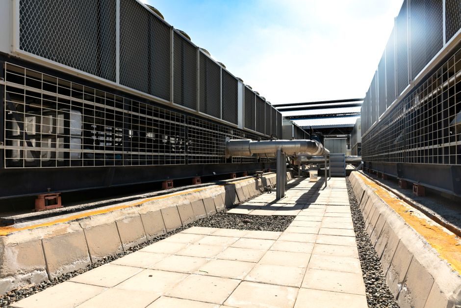
Thermal relays and brake resistors sit next to each other in variable-frequency-drive cabinets, but they protect completely different physical domains. A thermal overload relay is a bi-metallic, current-sensing protective device wired into the motor's main circuit and calibrated in amps (e.g. the Fuji TK-E02-420 at 2.8-4.2 A adjust range or the TK26E-P18 at 0.18-0.27 A) [S4][S5]. A brake resistor is a passive power resistor, sized in ohms and kilowatts, wired across the DC bus to absorb regenerative energy from a decelerating motor.
ABB frames the thermal overload relay as an "economic electromechanical protection device for the main circuit" that, paired with a contactor, handles overload and phase-failure conditions on standard induction motors [S1]. Engineers selecting one of the two should start by asking a single question: am I limiting motor heating, or am I bleeding off DC-bus energy? Once that is answered, the rest of the spec falls out of the catalog page.
Function and Physical Domain: Why They Cannot Be Substituted
A thermal relay's job is to model the I²R heating of a motor winding with a bi-metallic strip and trip the contactor when cumulative heat exceeds a threshold. ABB lists motor protection against overload and phase failure as the two headline use cases, which means the device samples line current and indirectly estimates rotor and stator temperature [S1]. A brake resistor does the opposite — it is a deliberate heat source. During regeneration the drive's DC-bus voltage rises; the brake chopper switches the resistor across the bus, and the resistor converts that electrical energy into heat that must be dumped to ambient. For background on the device class see the thermal relay and brake resistor encyclopedia entries.
Because the two are dimensioned in different units — amps and trip class for the relay, ohms and peak/continuous watts for the resistor — swapping one for the other is a wiring fault, not a configuration choice. A 4 Ω / 2 kW brake unit installed in a motor-protection slot will not sense overload; a 4 A thermal relay installed across a 700 V DC bus will fail open within milliseconds and provide no braking at all.
Sizing and Selection Criteria: A Side-by-Side Comparison
Selection for each device is driven by three parameters that do not overlap. For a thermal overload relay the spec engineer needs motor full-load amps (FLA), the desired trip class (Class 10, 20, 30), and the coordination type with the upstream contactor (Type 1 or Type 2 per IEC 60947-4-1) [S1]. For a brake resistor the spec engineer needs drive DC-bus voltage, peak braking power, continuous duty cycle (ED %), and resistance tolerance — typically ±10 % is acceptable for chopper stability.
The Fuji TK-E02-420 datasheet is a clean illustration of relay-side parameters: bi-metallic strip, local reset, 2.8-4.2 A adjust, and direct power connection to the SC-E series contactor [S4]. None of those fields appear on a brake-resistor datasheet, where engineers look for Ω, peak W, continuous W, and a thermal time constant — the same physical quantity that the MATLAB Simscape "Thermal Resistor" block parameterises via dissipation factor K_d and thermal time constant t_c [S3].
Real Application Scenarios and Misapplication Risks
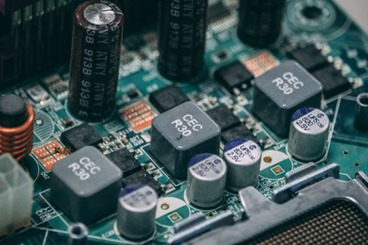
Thermal overload relays are the right call for direct-on-line motors, star-delta starters, and simple V/Hz drives where the goal is to protect the asset from stall, mechanical jam, or single-phasing. ABB explicitly markets this combination for motor starting under overload and phase-failure conditions [S1]. Brake resistors are the right call for high-inertia decel (centrifuge stops, crane lowering, hoist overhauling), four-quadrant servo systems, and any VFD application where the regen energy would otherwise trip the DC-bus over-voltage threshold.
The textbook misapplication is installing a brake resistor in place of a motor-protective device on a long-cable run, hoping the resistor's thermal mass will absorb a locked-rotor event. The resistor has no sensing element and no contactor interface, so a stalled rotor will simply overheat undetected. Conversely, trying to "brake" a 22 kW hoist by wiring a 4 A thermal relay across the DC bus will both fail to brake the load and destroy the relay's bi-metallic strip within seconds. Standards covering the broader contactor-and-overload assembly for motor starting (IEC 60947-4-1 family) explicitly treat the overload relay as a protective device, not a dynamic brake.
Spec Gates That Decide Lifecycle Cost
On the relay side, three spec gates decide whether the device survives its environment. First, the FLA adjust band must sit inside 110-125 % of motor nameplate current; outside that window, a Class 10 relay will nuisance-trip on cold start or under-protect on stall. Second, the trip class must match load inertia — Class 10 for normal starts, Class 20 for high-inertia fans and conveyors, Class 30 for very long acceleration ramps. Third, the ambient temperature rating around the cabinet must be derated: most bi-metallic relays are calibrated for 40 °C and lose roughly 1 % of trip current for every °C above that, so a thermal imager walk-around is standard practice to confirm the worst-case cabinet ambient. [S1]
On the resistor side, the spec gates are peak power, continuous power, and resistance tolerance, all tied to the drive's brake-chopper switching threshold. A typical 22 kW VFD on a 400 V line will look for a 20-30 Ω resistor rated for 5-10 kW continuous with 30-50 kW peak for 5-10 s. Under-sizing continuous power is the dominant failure cause — the resistor's enamel coating cracks, resistance drifts, and the drive eventually trips on bus over-voltage. The same thermal-time-constant logic that Simscape exposes for simulation — K_d and t_c — is exactly what a brake-resistor datasheet hides inside its "ED %" curve [S3].
Product Lifecycle and Sourcing Signals (2026)
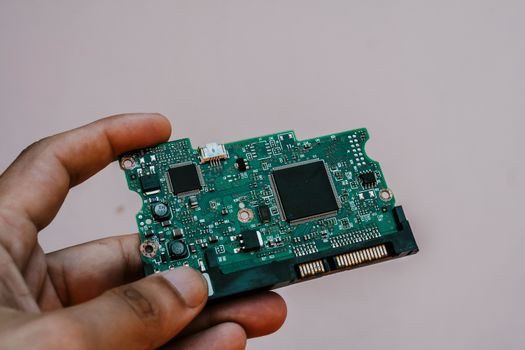
The Fuji SC-E-platform thermal overload relays cataloged by AutomationDirect show two relevant lifecycle events within the past 90 days: the TK-E02-420 is flagged as retired, and the TK26E-P18 is listed as discontinued in May 2026 with a direct-replacement search in progress [S4][S5]. For spec engineers maintaining SC-E02x through SC-E05x starter assemblies, this is the actionable signal — stock the equivalent adjust range from a current series before the line card rotates, and verify IEC 60947-4-1 Type-2 coordination with the substitute.
For a deeper comparison of related electromechanical protection devices — and the difference between an overload relay, a motor protector, and a circuit breaker — the motor protector selection guide lays out the trip-class and FLA logic in the same engineering language. None of the relay or resistor suppliers have announced brake-resistor cross-references against the SC-E retirement, so any apparent "drop-in" resistor on a third-party listing should be rejected on resistance tolerance alone.