
Tunnel construction runs hot, wet, dusty, and confined, and that combination is exactly what a plasma cutter spec sheet hides. A 60–130 A inverter source with 60% minimum duty cycle at 40 °C and an IP23S enclosure is the baseline for primary steel erection inside a bored or NATM tunnel [S2][S5].
The four most common industrial cutting routes (oxy-fuel, plasma, laser, waterjet) split on thickness, edge quality, and conductivity; plasma sits in the 0.5–50 mm mild-steel band and remains the dominant portable choice for plate under roughly 25 mm [S5]. In tunnel work, that window lines up with primary lining reinforcement, lattice girders, steel ribs (TH profile), invert rebar, and embedment plate.
Why Tunnel Sites Break Consumer-Grade Plasma Cutter Spec Sheets
Consumer-grade 20–30 A units (rated 1/8–3/16 in recommended cut, 1/4 in maximum) run on 120 V household outlets and are useful only for sheet-metal and HVAC tasks, not for structural tunnel work [S2]. The first spec gate is conductivity class: plasma cuts any electrically conductive metal (mild steel, stainless, aluminium, galvanised) and ignores the pre-heat that oxy-fuel demands on thick carbon plate, but it cannot cut stone, shotcrete, timber lagging, or HDPE/GRP drainage [S5]. A tunnel crew that buys a single plasma unit for steel plus a complementary tool for non-concrete is the correct logic; a plasma cutter alone will not cover invert trimming or segment handling.
Tunnel air is loaded with humidity, diesel particulate, and lime-clay dust, all of which the plasma air supply must reject. Compressed-air spec is 60–90 PSI (4–6 bar) at 4–8 CFM depending on amperage, and the line must be clean, dry, oil-free, or premature consumable failure and tip clogging follow [S2]. For a 60–80 A unit on a 6 CFM draw, a 60 gallon receiver plus an inline desiccant dryer is the minimum recommended package, sized the same way a construction machinery and equipment pneumatic circuit is sized [S2].
Amperage, Duty Cycle and Arc Start for Tunnel Duty
Industry shorthand holds at roughly 10 A per 1 mm of clean cut on mild steel for inverter-class machines; a 60 A unit is rated near 15–20 mm sever, and a 130–200 A mechanised source reaches 35–50 mm plate [S5]. For typical tunnel steel (TH ribs at 6–12 mm, lattice girder flats at 8–16 mm, embedment plate at 10–20 mm), 60–100 A at 60% duty cycle is the productive sweet spot. A 50 A cutter with only 35% duty cycle can run 3.5 minutes at 50 A then must cool 6.5 minutes, which destroys the cut-start rhythm of an erection shift and burns operator hours [S2].
Duty cycle at 40 °C ambient (60% or 100% on industrial models) sets how long the source delivers rated current before thermal cut-back [S5]. Tunnel invert temperatures regularly exceed 35 °C once ventilation is balanced for diesel equipment, so a 60% rating is the floor, not the ceiling. Piercing capacity is typically 50–60% of sever capacity on conventional plasma and approaches 100% on high-definition units, which matters when cutting 12 mm embedment plate on the formwork table [S5].
Arc-start logic should be pilot-arc (HF or contact) rather than pure scratch start; pilot arc fires on painted, galvanised, or rusty plate without retracing, which is the everyday surface condition in a tunnel yard [S2]. This is the same arc-start spec gate that demolition crews use; readers working in adjacent heavy-civil work can see the parallel in the demolition spec map.
Cut Quality, Consumables and Operating Cost Underground
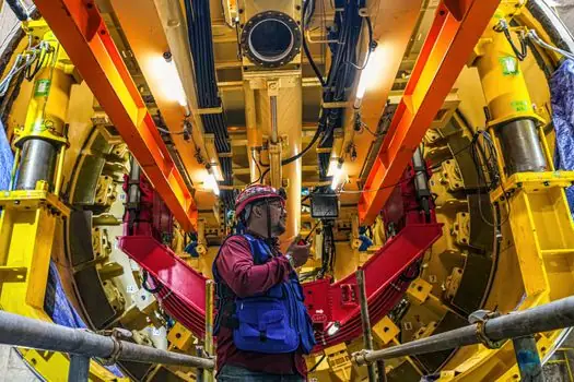
Conventional plasma leaves a 3–8° top-to-bottom bevel on 10–25 mm cuts; high-definition (fine-grain) plasma with constricted nozzles and nitrogen or argon-hydrogen shielding drops that to under 2° on stainless and aluminium [S5]. Kerf runs 0.8–1.5 mm depending on nozzle orifice and current, and dross on the bottom edge is the cleanest single indicator of gas-flow and standoff health. For tunnel rib splices that feed straight into a backing-rod and grout joint, a 3–5° bevel is acceptable, but for embedment plate that bolts to a gasket face, high-definition cuts pay back in eliminated re-work.
Consumables (electrode, tip, swirl ring, shield, retaining cup) sit in the torch head and wear; a 40 A drag tip on 6 mm mild steel typically lasts 60–120 pierces, while a 200 A mechanised nozzle on 25 mm stainless can exceed 800 pierces before bore erosion widens the kerf [S5]. Three levers move consumable cost underground: standoff distance (drag vs mechanised), gas purity (instrument-grade air vs shop air with desiccant), and pierce technique (ramp pierce vs on-plate pierce). Standardising torches that accept the same consumables family collapses the parts shelf from dozens of SKUs to a handful, which matters when the only resupply is the surface warehouse at the end of a 2 km adit.
Comparison: Handheld vs Mechanised vs CNC Plasma for Tunnel Work
Three plasma platforms compete inside a tunnel, and the choice is driven by cut length, repeatability, and shift length, not by brand. [S5]
Handheld inverter 40–50 A, 35–60% duty, 120/240 V dual voltage, 4–5 CFM air, 1/4–3/8 in recommended cut, best fit: rebar trim on the invert, utility crosscuts, patch plate, repair work. Mechanised gantry 60–100 A, 60% duty at 40 °C, 240 V dedicated 30–50 A breaker, 6 CFM, 3/8–1/2 in recommended cut, best fit: rib splicing stations, embedment plate prep, lattice girder flats. High-definition CNC 130–200 A, 100% duty at 40 °C, 6–8 CFM, nitrogen or argon-hydrogen shielding, under 2° bevel, best fit: gusset plate cells on the surface yard, segment rebar cages where edge geometry feeds a robotic welder [S2][S5].
Rule of thumb: buy 20–30% more amperage than your typical material thickness for clean cuts and longer consumable life, a sizing margin that holds across tunnel applications the same way it holds for road maintenance fleet plasma sizing [S2].
Air, Power and Ventilation Constraints Inside the Tunnel
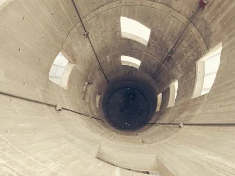
Input power on tunnel work is almost always 240 V at 30–50 A dedicated circuit; 120 V units cap at 30–40 A and 3/8 in recommended cut, which is below the structural threshold for ribs and girders [S2]. Twin generators are common in NATM drives, and a plasma source sharing a generator with shotcrete pumps and fans needs a soft-start or a dedicated feeder to avoid nuisance trips on arc ignition.
Ventilation interacts with plasma fume output in two ways. Stainless cutting releases chromium-bearing fume; galvanised rebar trim releases zinc-bearing fume; both require extraction and respiratory protection independent of the tunnel's main ventilation [S3]. A water table beneath the plasma bed is the standard method for capturing particulate and is mandatory for any aluminium cutting, where water reacts with molten metal, and for galvanised work where it reduces airborne zinc. Compressor placement matters: a diesel compressor in a confined heading elevates NOx, and an electric compressor is the safer pairing for plasma work within 50 m of the face.
Selection Criteria Buyers Should Lock First
Six spec gates screen a plasma cutter for tunnel work, and the first three disqualify the majority of consumer units. Gate 1: material thickness 6–25 mm mild steel dominant; Gate 2: amperage 60–100 A minimum, duty cycle 60% at 40 °C minimum, pilot-arc start; Gate 3: cut quality under 5° bevel on 10–20 mm plate, kerf under 1.5 mm; Gate 4: consumables family with documented arc-on minutes and pierce counts at the operating amperage; Gate 5: air supply sized to 6 CFM minimum with desiccant dryer; Gate 6: enclosure IP23S or better, weight under 35 kg for hand-carry up a cross-cut [S2][S5].
A unit that passes gates 1–3 but fails on consumable commonality or enclosure rating is still a misbuy; consumable shelf depth and ingress protection are what separate a tunnel-rated source from a shop-floor unit moved temporarily underground.
Failure Modes and Limits in Tunnel Service
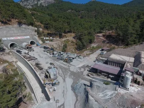
Three failure modes show up repeatedly. First, thermal cut-back during a long rib splice when the operator runs above the rated duty cycle; the source throttles back to protect the IGBT stack, and the cut quality collapses to a curved dross-heavy edge. Second, consumable starvation when the desiccant dryer is undersized or bypassed; tip life drops from hundreds of pierces to dozens, and bottom-edge dross reappears. Third, HF-start interference with the tunnel's leaky-feeder communication system and with adjacent laser guidance; pilot-arc contact-start torches are the workaround on heading work where any RF is regulated. [S5]
Plasma does not replace oxy-fuel on thick plate above roughly 50 mm, and it does not replace waterjet or diamond saw on the concrete, stone, or HDPE drainage components of a tunnel cross-section; for those materials the correct tool family is a concrete groove cutter, a marble cutter, or a rebar cutter, not a plasma source [S5]. Specifying a plasma cutter for a concrete cut is a common RFQ error worth catching at the inquiry stage.
Track the next data point on 2026-09-15 when the European industrial gas suppliers update their bulk cylinder pricing for nitrogen and argon-hydrogen shielding gas, since the high-definition cut premium depends on that line item. Also worth tracking: the next revision cycle of the IEC 60974 series for plasma safety, which sets the touch-current and insulation test thresholds cited on every CE-marked cutter nameplate.