A modern power grid is a four-stage value chain — generation, HV transmission, substation transformation, and LV distribution — governed by synchronous electromechanical physics, fault-current limits, and a growing digital control layer (IEC 61850, IEEE C37.2, NERC reliability standards) [S1][S2].
Grid production technology is the engineering stack that decides frequency stability (50/60 Hz), short-circuit MVA, harmonic distortion (IEEE 519), and renewable hosting capacity. The 2026 driver list is concrete: HVDC backbones, grid-forming inverters, distribution state estimation, and open-source power-flow solvers [S2].
Generation Stage: Synchronous, Inverter-Based, and Hybrid Plants
Synchronous generators in 2026 are still specified around four poles at 50 Hz (1500 rpm) or 60 Hz (1800 rpm), with typical turbo-generator outputs of 100–1500 MW and hydro units of 1–800 MW per machine. The 2% voltage regulation and 5% frequency droop characteristics are still the default grid-forming behaviour [S1].
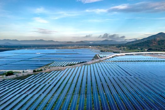
Renewable generation — utility-scale PV and onshore/offshore wind — is now dominated by Type-3 and Type-4 inverters (IEEE 1547-2018) that interface via DC-link and IGBT stacks. Inverter-based resources (IBRs) introduce sub-synchronous oscillations and reduced inertia, forcing TSOs to mandate grid-forming controls and synthetic inertia from 2024 onward on new connections [S1].
The hybrid plant — solar + BESS + STATCOM on a single POI — has become the standard utility bid since 2023. Typical block sizes are 50–250 MW PV with 1–4 hour batteries delivering 25–100 MW, coupled with ±20–60 MVAr STATCOMs for reactive support, all tied to a 33/66/132/220 kV substation via step-up power transformers [S1].
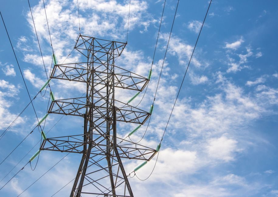
HV Transmission: AC Overhead, Underground, and HVDC Backbones
HV AC transmission classes remain 110/132 kV, 220/230 kV, 400/500 kV, and 765/800 kV. Conductor selection (ACSR, AAAC, ACSS, HTLS) controls ampacity; HTLS conductors such as ACCC or ACSS/TW can raise thermal limits 50–100% over ACSR of the same diameter [S1].
HVDC links — VSC-based (using IGBT/IGCT stacks) for ±320 kV and ±525 kV cable systems, and LCC-based (thyristor valves) for ±800 kV and ±1100 kV overhead — are the workhorses of bulk long-haul and offshore-wind export.
Substation comms run on IEC 61850 with GOOSE messaging under 4 ms and Sampled Values (IEC 61869-9 process bus). Protection follows IEC 60255 (overcurrent, distance, differential 87L) with arc-flash mitigation via IEC 61850-based fast bus transfer [S1].
Distribution Stage: MV Feeder, LV Network, and DER Hosting
MV distribution operates at 6.6/10/11/13.8/20/33 kV, feeding LV at 220/230 V single-phase or 380/400 V three-phase. Typical LV feeder is 200–400 m with voltage drop budget 5%, and distributed PV penetration is now constrained by thermal limits and voltage rise rather than by generation [S3].
Distribution state estimation — running on a three-phase unbalanced model with smart-meter SCADA inputs — is the 2026 baseline. The open-source Power Grid Model library (C++ core, Python/C bindings) supports power flow, state estimation, and short-circuit calculation on networks of 1k–10M+ nodes, with iterative solvers handling large DER fleets [S2].
The 7 kW residential EV charger myth — that "the grid cannot handle EVs" — is largely false: per Digital Trends, off-peak smart charging shifts the load; the real constraint is local transformer and feeder thermal limits, not bulk generation. Distribution utilities are now deploying power meter AMI at 15-minute intervals and dynamic line ratings to free 20–30% of feeder headroom [S3].
Comparison: AC vs HVDC Transmission vs Smart Distribution
Decision criteria for new bulk transfer: distance, power level, controllability, and footprint. AC overhead wins below 400 km and under 2 GW per circuit; HVDC VSC wins for 100–800 km subsea cable or 1–3 GW point-to-point; HVDC LCC wins above 1000 km and for 5+ GW backbone capacity. AC needs synchronous stability and reactive compensation; HVDC decouples and provides black-start capability (VSC with grid-forming) but costs more at the terminal [S1].
Smart distribution comparison: traditional radial MV feeder (low cost, low reliability, SAIDI ~120 min/yr) versus automated looped feeder with reclosers and Sectionalising Switches (medium cost, SAIDI ~30 min/yr) versus fully meshed microgrid with DER + BESS (high cost, SAIDI <5 min/yr, islanding-capable) [S2].
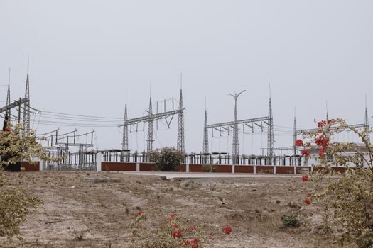
Substation Equipment: Transformers, Switchgear, and Power Cabling
On-load tap changers (OLTC) provide ±10–16% range in 16–33 steps for grid voltage regulation [S1].
MV switchgear at 11/33 kV is dominated by vacuum interrupters (IEC 62271-100) with 31.5–40 kA short-circuit rating; HV SF₆-free GIS at 145/245/420 kV uses vacuum or CO₂/O₂ mixture as the dielectric (IEC 62271-203). SF₆ phase-out pressure is real: EU F-Gas regulation pushes utilities to 145 kV SF₆-free GIS since 2024 pilots [S1].
LV and MV power cable selection is governed by IEC 60502-1 (≤1 kV) and IEC 60502-2 (6–30 kV). Cross-linked polyethylene (XLPE) insulation at 90°C continuous / 250°C short-circuit allows 100–630 mm² Cu or Al conductors, with armour options SWA/SWA-FR for direct burial. For HVAC export, 220 kV XLPE submarine cable is now standard at 600–1400 mm² Cu [S1].
Stability, Protection, and ICT Layer
Grid frequency must hold ±0.5% nominal on interconnected systems (50/60 Hz), with RoCoF limits typically 1 Hz/s. Inertia constant H of 3–6 s for a thermal plant gives the kinetic buffer; IBRs replace it with synthetic inertia and fast frequency response (FFR) under 1 s [S1].
Protection coordination follows IEC 60255-151 (overcurrent), IEC 60255-121 (distance), and IEC 60255-118 (differential). The ICT/SCADA layer — IEC 61850 at substation, IEC 60870-5-104 at control centre, IEEE C37.118 for PMU/WAMS — is the 2026 attack surface; ICT-based monitoring and control of PV plus battery plus grid assets is now a published design path with MATLAB/Simulink validation [S4].
Quality of supply targets THD <8% at LV (IEEE 519) and voltage unbalance <2%. Active harmonic filters and STATCOMs handle the rest. The power mixer term in distributed generation refers to power-aggregation inverters that mix PV, BESS, and diesel-gen into a single grid-compliant waveform [S4].
Selection Criteria for New Grid Build vs Retrofit
Greenfield 2026 grid: HVDC VSC backbones (≥500 km), IBR-heavy generation, IEC 61850 process bus, SF₆-free GIS, AMI smart meters, distribution state estimation. CAPEX per km is 2–5× higher than brownfield, but SAIDI and renewable hosting capacity improve 3–10× [S2].
Brownfield retrofit: HTLS conductor reconductoring (raises ampacity 50–100% without new towers), distribution automation with reclosers/sectionalisers, dynamic line rating (DLR) sensors, and BESS for peak shaving. Lead time 12–24 months versus 5–8 years for greenfield, and CAPEX 30–50% lower [S2].
Failure Modes and Engineering Constraints
Thermal limit on power cable and overhead line: ampacity is set by conductor temperature (90°C XLPE, 75°C ACSR) and ground ambient. Voltage drop and short-circuit withstand (1 s/3 s Ik) are the parallel constraints. Underground HV is 5–10× the cost of overhead per km, justified only in urban or environmentally restricted corridors [S1].
Stability failure modes: voltage collapse (reactive reserve exhaustion), angle instability (loss of synchronism after a fault), frequency instability (insufficient inertia during IBR-heavy operation), and sub-synchronous resonance from series-compensated lines. Each is mitigated by a specific tool — STATCOM, PSS, fast frequency response, or TCSC damping [S1].
Standards, Sourcing, and Trackable Signals
Core standards for 2026 grid production: IEC 60076 (transformers), IEC 62271 (switchgear), IEC 60255 (protection), IEC 61850 (substation comms), IEEE 1547 (DER interconnection), IEEE 519 (harmonics), IEC 60870-5-104 (control centre), and IEC 61970 CIM (data model). Sourcing channels include major utilities' procurement portals, TSO framework agreements, and open-source power-flow tooling on GitHub [S2].
Trackable 2026 signals: SF₆-free GIS rollout at 145–420 kV (EU F-Gas), grid-forming inverter mandates (Australia, Ireland, Texas), HVDC interconnector commissioning (North Sea, Mediterranean), and 800 V DC data-centre distribution pilots feeding back into utility-grade equipment. Watch the power semiconductor production pipeline — every IGBT and SiC module that lands in 2026 becomes a grid-forming inverter or STATCOM by 2027, and converter power supply density on a substation bay is the next cost curve to fall.