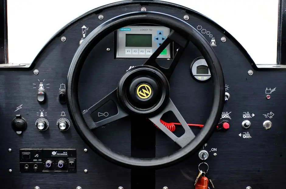
On a hydraulic test bench a pressure switch is the discrete element that decides when a hydrostatic test cycle aborts, vents, or holds, and it is the component most often underspecified [S1][S3].
Suncenter’s hydrostatic pressure test pump range covers 0–6000 bar with paper round-chart recorders, which is the duty envelope that any switch on such a rig has to survive without drift [S1].
Working pressure, proof pressure, and burst margin
The first selection number is setpoint range versus proof pressure: most industrial pressure switch datasheets are built around a 1.5× proof to operating ratio, with 2× available for cyclic test stands [S3]. A bench running at 400 bar working pressure therefore needs a switch rated for at least 600 bar proof, and preferably 800 bar, before repeatability degrades.
Hydraulic test benches built around pneumatic-driven liquid pumps (air-driven liquid pump, hydraulic test pump) inherit pulsation from the drive gas, so a switch with a wider deadband reduces relay chattering near the cut-out point [S1]. For hydrostatic test machines rated to 600 MPa, separate low-pressure and high-pressure switches wired in series are the usual practice so each device works in its optimum 30–70% range of full scale.
Mechanical vs electronic pressure switch: switching behaviour
Mechanical snap-action pressure switches (bourdon, diaphragm, piston) typically give a fixed hysteresis of 5–15% of setpoint and a repeatability of ±1–2% FS, with electrical ratings up to 5 A at 250 VAC on the SPDT contact [S3]. They survive vibration, hydraulic shock, and contaminated oil without auxiliary power.
On a hydraulic test bench with PLC-controlled ramp-and-hold cycles, the electronic variant removes the need for a separate pressure transmitter and lets the same device drive both the trip relay and the data logger. For a comparison on test-bench duty, three credible options are:
1) Mechanical piston switch (e.g. 100–600 bar, IP65, G1/4): lowest cost, no power needed, widest media compatibility, but fixed hysteresis and contact wear after ~1 million cycles.
0–600 bar, two PNP/NPN outputs, IO-Link): adjustable setpoint and deadband, but needs 24 VDC supply and is less tolerant of pressure spikes above 1.5× range.
3) Hydraulic test rig with combined transmitter + mechanical cut-out: 4–20 mA for the chart recorder plus a separate mechanical switch as a fail-safe overpressure trip, which is the configuration found on most OEM hydrostatic test pumps up to 6000 bar [S1].
Media compatibility, wetted parts, and sealing

Wetted material is the second hard gate after pressure rating. Mineral hydraulic oil (HLP 32/46) is benign, but ester-based or water-glycol (HFC, HFA) fluids attack nitrile seals, and phosphate ester (HFD-R) attacks most elastomers except Viton/EPDM. A 316L stainless port with FKM (Viton) seals and a Hastelloy diaphragm covers the bulk of test-bench chemistry; brass or plated carbon-steel bodies are acceptable only on oil-only benches and are not suitable for water-glycol or ester fluids. [S1]
Process connection is usually G1/4 or G1/2 BSPP, with NPT or 7/16-20 SAE available for North American rigs; high-pressure fittings above 1000 bar should be coned-and-threaded (e.g. 1/4 HP cone) or Autoclave-style, not standard tapered pipe threads. A static O-ring seal on a parallel thread (BSPP, SAE O-ring boss) is preferred to tapered threads, which are prone to galling and to creeping leaks across many thermal cycles.
Electrical rating, ingress protection, and zone classification
Switch contact rating has to be matched to the load, not to the line voltage. A 250 VAC / 5 A SPDT contact handles an inductive motor contactor coil; for DC solenoid valves on 24 VDC, look for a switch rated for at least 2 A DC and ideally gold-plated contacts to prevent oxide buildup. For test and measurement racks in a control cabinet, an IP65 or IP67 rating is the floor; bench-mounted switches that get splashed by hydraulic oil should be IP67 with a flying lead or M12 connector, not a bare DIN plug. [S1]
For test benches in hazardous areas (refinery skid test, LNG component test) the switch body needs ATEX Ex d or Ex ia marking matching the zone, with the entity parameters of the intrinsically-safe barrier checked against the switch’s Ui, Ii, Pi. In non-classified areas a simple industrial pressure switch with a CE-marked enclosure is sufficient, but the cable gland and conduit entry still have to meet the IP code stated on the nameplate, otherwise the rating is void. Specifiers building out a full electronic test panel should keep the pressure switch on its own fused branch so a short does not drop the data acquisition.
Setpoint configuration, hysteresis, and how the bench uses it

Setpoint type dictates how the switch sits inside the test sequence. A normally-open (NO) contact closes on rising pressure and is the standard choice for a cut-out at upper limit, then the PLC vents the circuit through a separate solenoid. A normally-closed (NC) contact is used for a low-pressure alarm that triggers when the pump loses prime or a hose ruptures. A SPDT (changeover) contact gives both states from one device, useful on a valve test bench where the pass criterion is pressure held within a band for a set dwell time. [S1]
Hysteresis (deadband) is the difference between cut-in and cut-out pressures, and on a hydraulic test rig running 5–20 bar/s ramps, too small a deadband causes relay chatter, while too large a deadband means the overpressure trip fires well above the intended limit. For a 400 bar hydrostatic test of a hydraulic accumulator, a 10–20 bar deadband (2.5–5% of full scale) is the practical working window.
Who should pick mechanical, and who needs electronic
Mechanical switches are the right call on simple hydrostatic test pumps (fire extinguisher filling machine, LPG pump, FM200 automatic filling machine type benches) where the operator presses start, watches the chart, and walks away, and where no PLC is involved. They are also the safer pick as a hard-wired overpressure cut-out in series with an electronic transmitter, because a mechanical switch fails open or closed predictably even when the 24 VDC rail is dead. [S1]
Electronic switches belong on benches with ramp-and-hold profiles, data logging, or remote setpoint change, where the same device can serve as the pressure switch, the chart recorder input, and the alarm source. They are the wrong call on high-cycle production test stands (more than ~30 cycles/h) if the solenoid output is mechanical, because solid-state outputs still dissipate heat in the load and need a flyback diode on 24 VDC coils.
Verification, standards, and a pre-purchase checklist
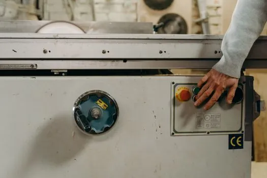
Before signing off on a switch for a hydraulic test bench, five numbers have to appear on the datasheet: setpoint range with adjustment span, proof pressure (1.5× working minimum), burst pressure (≥4× working is typical for diaphragm designs), electrical rating under the actual load type (AC-1 / DC-13), and IP rating with the gland type. A 1.5× proof figure, 5 A / 250 VAC SPDT contact, and IP65 are the minimum datasheet bars for a bench-scale hydraulic test loop. [S1]
Cross-reference the device against the test medium under the planned ambient temperature range, since most NBR seals are derated above 80 °C and most FKM seals are derated below -20 °C; for outdoor test rigs specify a low-temperature elastomer and a heated enclosure. For traceable calibration, specify a switch with a 3.1 material certificate on the wetted parts and a calibration certificate traceable to national standards; on hydrostatic test machines rated above 600 MPa this is a contractual requirement from most third-party inspection bodies, not a nice-to-have [S1].
One last trackable signal: most OEM hydrostatic test pumps up to 6000 bar pair the chart recorder with one mechanical high-pressure cut-out and one electronic pressure transmitter, and the next spec-cycle shift is the migration of the mechanical element into the transmitter firmware, with the mechanical switch kept only as a SIL-rated backup.
See also our earlier report, Rebar Coupler Selection for Steel Construction: 2026 Spec Map.