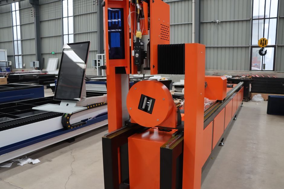
A riser cutting machine is installed correctly when the foundation, electrical, and coolant loops are signed off before any blade tension is applied — and on a Multicut VBM-150 that floor footprint is 1000 x 1000 x 1610 mm supporting a 550 kg chassis with a 3 HP main drive and a 0.14 HP coolant motor [S2].
This guide covers the install steps that foundry and pattern-shop engineers actually own: foundation and levelling, power and coolant routing, blade break-in, and the first-cut acceptance window for a typical vertical band-saw class riser cutter such as the VBM-150, plus where the riser cutting machine sits inside the broader cutting machine family.
Foundation, Floor Space, and Levelling Tolerance
The VBM-150 ships at 550 kg gross weight with a 1000 x 1000 x 1610 mm (L x W x H) envelope and a 500 x 500 mm work table, so the floor pad must be rated for at least 700 kg/m² point-plus-distributed load with a 50 mm perimeter clearance for chip pan and coolant drain access [S2]. On a concrete industrial floor, an 80 mm thick M25 concrete pad with anchor bolts set at the four machine feet is the typical hold-down detail for this class; shim under each foot until the column reads ≤ 0.05 mm/m verticality on a precision level before grouting, because out-of-level columns pull the band wheels off the centreline and the throat reading (250 mm on the VBM-150) drifts away from the published spec [S2]. For facilities with raised access floors, the same 550 kg loading must be carried by adjacent floor panels and pedestals; do not bridge a panel joint under the table.
Coolant containment is part of the foundation design, not an afterthought: position the machine so the floor slope falls 1:100 toward a dedicated floor drain within 1.5 m of the coolant outlet, and route the 0.14 HP coolant motor discharge through a fine mesh strainer before the drain to keep foundry swarf out of the process water system [S2]. Acceptance at this stage: dial-indicator runout on the table ≤ 0.05 mm across the 500 x 500 mm surface, and a 24-hour loaded deflection check on the floor pad reading ≤ 0.02 mm before any cutting cycle is run.
Power, Coolant, and Cable Routing
The VBM-150's main 3 HP drive and 0.14 HP coolant motor run from a three-phase supply with a dedicated MCCB sized for the inrush of the band drive; a phase-failure relay is mandatory because bandsaw motors exposed to single-phasing will burn the start winding within a few stall events [S2]. Cable routing follows the same separation rules used on a linear guide retrofit or any other CNC-class install: keep power cables at least 150 mm away from any signal or encoder lines, secure both with cable ties, and leave a service loop at every connector so the door and blade-guard interlocks can be opened without straining the harness [S7].
Coolant plumbing: connect the 0.14 HP coolant pump to a flood nozzle positioned to deliver 8–12 L/min at the blade entry point, with a solenoid valve wired to the machine's work-area guard interlock so the pump can only run when the guard is closed and the band is in motion [S2]. The first 30 minutes after power-on should be a no-cut dry test of the coolant pump direction, the interlocks, and the emergency-stop loop, with a multimeter reading of the motor insulation to ground before any live cut. Acceptance: insulation resistance ≥ 1 MΩ at 500 V DC on both motors, E-stop trip time ≤ 50 ms, and coolant flow at the nozzle within ±10% of the setpoint.
Blade Selection, Tracking, and Manual Tension
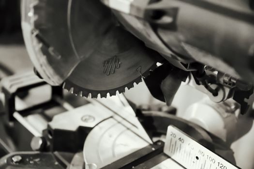
The VBM-150 uses a 3000 mm blade running between two band wheels with a 250 mm throat and a 20–100 m/min band-speed range; the spec sheet calls out manual blade tension, not hydraulic, so the install checklist must include a tensiometer reading and a tracking check before any production cut [S2]. Blade choice for cast-iron risers from 100 mm to 200 mm section — the same range quoted on the Chanditex high-precision heavy-duty raiser cutting SPM — is a bi-metal variable-pitch 3/4" x 0.035" tooth with 4/6 TPI, which clears the swarf faster than a constant-pitch blade on interrupted cuts [S4].
Commissioning sequence: mount the blade, set tracking by adjusting the upper band wheel's tilt until the blade rides centred on the wheel crown, then bring tension up in 10% increments and let the machine idle for 5 minutes at 30 m/min to seat the blade on the wheels. A blade that walks forward or backward under this idle run is incorrectly tracked and will cut a tapered riser face. Acceptance: blade runs within ±1 mm of the wheel-flange centre for at least 10 minutes of no-load run, and a 100 mm aluminium test block produces a square cut face within 0.1 mm/m perpendicularity and a clean, burr-free exit side.
First-Cut Acceptance, Foundry Use, and When to Escalate
Gates and riser cutting machines automate the removal of runners, gates, and riser stubs from cast iron, aluminium, and steel components, so the first production cut on a VBM-150 should be a known scrap casting of the largest section the machine is rated for — 150 mm on the VBM-150 — with the work table locked and the operator stationed outside the immediate line of cut [S2][S5]. A clean first cut leaves a flat, uncracked riser stub at the casting surface with no tooth marks and no heat tint; any tooth chatter, blueing, or surface cracking is a sign that band speed is too high, the tooth pitch is too fine, or coolant flow is starving the cut [S5].
Use a production riser cut when: the section is within the 20–100 m/min band-speed window, the material is cast iron up to 150 mm, and the operator can keep both hands clear of the cut line. Do not push the VBM-150 into 200 mm+ cast-iron sections or hardened-steel risers on the manual-tension class of machine — that is a hydraulic-tension and powered-feed machine class, and forcing it will stall the 3 HP drive and trip the overload. For foundries running high-mix small batches, a crossed roller guide retrofit on a horizontal bandsaw is the better fit; for the manual table-and-throat class that the VBM-150 represents, the install acceptance list above is sufficient. Escalate to the OEM when insulation resistance drifts below 1 MΩ on the quarterly check, when coolant flow cannot hold ±10% of setpoint, or when the blade tracking cannot be centred after two tension-and-track cycles.
Trackable signals for the next maintenance window: log the first 50 production cuts with band speed, section size, coolant flow, and blade-tension setting, then schedule a re-tension at the 50th cut or the 80-hour mark, whichever comes first.
This topic is covered further in Coating Thickness Gauge Buying Guide 2026: Substrate, Range, Standard.