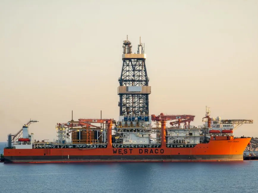
For pipeline construction, a rotary drilling rig is the primary tool when the route crosses roads, rivers, rail corridors, or urban utilities, and the contractor needs to install a product pipe without open-cut trenching. Trenchless rigs in this class typically deliver 15–25 t of pullback for short telecom/electrical crossings up to 200 m, 40–80 t for 300–500 m gas or water mains, and ≥100 t when the crossing exceeds 600 m or the pipe diameter is DN600 or larger [S4].
The unit on the drill site is doing two jobs at once: it rotates a downhole tool to cut the formation, and it pulls the reamer and product pipe back through the pilot hole. Rated pullback, rotary torque, and feed/back-reel speed are the three numbers that decide whether the bore finishes in a shift or stalls halfway across a river [S2][S4].
Pullback Force: Sizing the Rig to the Crossing
Pullback force is the rig's ability to drag the reamer or product pipe back through the borehole, and it is the single number that gates maximum crossing length and pipe diameter [S4]. For DN200 power or telecom conduits up to 200 m, 15–25 t of pullback is normally sufficient; for DN300–DN500 water or gas mains across 300–500 m, plan on 40–80 t; for any crossing beyond 600 m or pipe diameter DN600 and up, the rig needs ≥100 t of rated pullback [S4].
The industry working rule is to specify the rig at 1.3–1.5× the expected maximum drag force calculated from pipe weight, buoyancy, and borehole friction, so the unit is not running at its absolute ceiling on the day of pullback [S4]. A hydraulic rotary rig with a 50 kN·m torque head (for example the YG13-class machine) can usually be matched with mid-range trenchless drills when the formation is soft soil or stiff clay [S3][S5].
Rotary Torque: Matching the Head to the Formation
Rotary torque, expressed in N·m or kN·m, is what actually breaks the formation, and it must be matched to the weakest section of the bore path, not the average section [S4]. Soft soils and ordinary clay are drilled comfortably with 4,000–6,000 N·m of torque; hard clay and dense sand need 8,000–12,000 N·m; cobble, weathered rock, and competent hard rock call for ≥15,000 N·m, typically combined with rock-cutting tools such as tricone bits or pneumatic DTH hammers [S4].
On a typical pipeline alignment, the deepest pile for a bridge pier or pump-station foundation uses a hydraulic rotary rig with 50 kN·m of torque, a 600–1,600 mm hole diameter, and a 13 m drill depth, with the gear pump delivering 80 ml/r at 20–25 MPa of hydraulic working pressure [S3]. The drive head rotates at 10–45 r/min on small tracked units, and the heavier 17.8 t carrier provides the downward crowd force that keeps the bit engaged in mixed clay-and-gravel profiles [S5].
Drill Pipe, Rod, and Diameter Selection
Drill pipe diameter controls both the steerability of the pilot string and the maximum reamed borehole size, and the rule of thumb is straightforward: small-diameter pipe (Φ60–73 mm) suits short crossings and small product pipes, while Φ89–127 mm pipe is used for longer runs and larger-diameter reaming [S4]. For foundation work alongside the pipeline, the rotary rig typically runs a 13–20 m drill string, 1,000–1,600 mm hole diameter, and a 180° or 360° rotation head depending on slope and adjacent structures [S5].
Rotary angle is not a marketing detail. A 360° head (for example the YG13 or YG20 series) lets the driller keep working on sloped right-of-way or close to existing utilities, where the carrier cannot reposition; a 180° head is acceptable on flat, open pipeline yards but will force repositioning wherever the rig has to drill at an angle to the chassis [S5]. For trenchless crews, the same logic drives pipe-rack layout: long drill strings need clear lateral space for pipe handling, otherwise cycle time is lost to manual rod tripping.
Feed Speed, Mud Systems, and Cycle Time
Feed and back-reel speed typically range 0–20 m/min, but the practical rate is set by the formation and the drilling-tool combination, not by the hydraulic capacity of the rig [S4]. On long crossings (>500 m), specify a rig with automatic hydraulic matching of speed and torque, otherwise the operator is hand-balancing crowd and rotation under changing downhole conditions [S4].
Mud management is the second half of the cycle. Hydraulic rotary rigs using static mud-wall protection produce a thinner, rougher filter cake on the borehole wall, which improves pile side friction and reduces bottom sediment, and dry or low-mud circulation cuts fluid consumption to 1/10–1/20 of a conventional circulation rig [S3]. For trenchless pipeline pulls, an optional mud pump (a typical add-on priced around $4,500 on mid-range rotary packages) circulates drilling fluid to clear cuttings and cool the bit, and a starter set of three bits (soft clay, hardpan, rock) runs roughly $3,200 [S5].
Who the Rotary Rig is For, and Where it Fails
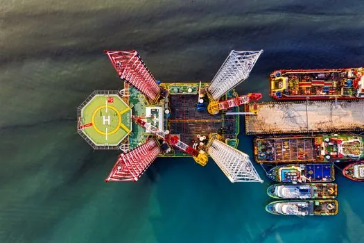
A pipeline contractor should be looking at a rotary drilling rig when the alignment crosses paved roads, rail corridors, rivers, or built-up urban blocks where open-cut is not permitted, and the product pipe is DN200 or larger with a crossing length of 200 m or more [S4]. A small wheeled rotary with 50 kN·m torque, 600–1,600 mm hole diameter, and 13 m drill depth is also the right tool for shallow pier foundations, valve-station piles, and pump-station anchor blocks in clay, sand, gravel, or moderately weathered rock [S3].
It is the wrong tool when the bore path runs through solid igneous rock for any significant length, when the crossing is short enough that a guided auger bore or pipe-ramming tool is cheaper, or when the site cannot accept an 8–18 t carrier and the mud-handling footprint that comes with it [S3][S5]. For purely trenchless pipe work where the formation is consistent soft clay, a smaller horizontal directional drilling (HDD) rig is usually more efficient than a full rotary piling machine, and rotary piling rigs remain the workhorse for foundation work adjacent to the pipeline rather than for the trenchless pull itself.
Comparison: Trenchless HDD vs Rotary Piling for Pipeline Work
Two machine families compete for pipeline construction budgets, and the decision is usually about what the rig is doing underground, not what it looks like on site. A horizontal directional drilling (HDD) rig is a trenchless unit designed for non-excavation pipeline installation, with surface disruption kept to the entry and exit pits; it is rated by pullback in tons and is the standard machine for road, river, and utility crossings [S1][S2]. A hydraulic rotary piling rig is a foundation machine with high-torque rotation, telescopic Kelly bar, and a drill bucket, used to form bored piles for bridge piers, building foundations, and any heavy anchor block along the pipeline right-of-way [S3].
On four decision criteria the two diverge clearly. Pullback and crossing length: HDD rigs lead, with 15–25 t for short runs, 40–80 t for mid-range, and ≥100 t for 600 m+ crossings; rotary piling rigs are not rated for continuous pullback. Rotary torque and pile quality: rotary piling rigs lead, with 50 kN·m heads and static mud-wall protection that lifts single-pile bearing capacity by 20–40% versus conventional circulation; HDD rigs typically run 4,000–15,000+ N·m depending on formation. Site footprint: rotary piling rigs need 8–18 t carriers and mud-handling space; HDD rigs need a clear drill-string side rack and entry/exit pit geometry. Best-fit use: HDD for the pipeline pull itself, rotary piling for the foundations and anchor structures that the pipeline sits on [S3][S4][S5].
Specifications Worth Tracking on the Datasheet

Before signing a purchase or rental order, a process engineer should see four numbers on the OEM datasheet, not adjectives: rated pullback in tons (or kN), maximum rotary torque in kN·m, maximum hole diameter in mm, and maximum drill depth in m. A typical mid-range hydraulic rotary rig lists 50 kN·m torque, 1,000–1,600 mm hole diameter, 13–20 m drill depth, an 88 kW engine, and a hydraulic system working pressure of 20–25 MPa, with the full 360° rotation head reserved for the heavier 17.8 t carrier [S3][S5].
For trenchless pipeline drills, the equivalent datasheet line items are pullback force (t), rotary torque (N·m), spindle speed (r/min), drill-pipe diameter (mm), and mud-pump flow rate; the standard sizing rule is 1.3–1.5× the calculated peak drag force, and the standard torque rule is ≥15,000 N·m once the bore path enters weathered rock or cobble [S4]. A short quotation worth keeping on file: "Select the rated pullback force of the drilling rig according to 1.3-1.5 times the expected maximum drag force, leaving room to cope with changes in actual working conditions" [S4]. New units in the 13–20 m class ship with a 12-month warranty and a 2-hour factory test run; used inventory typically carries a 6-month warranty [S5].
Track these signals over the next planning cycle: the working envelope of trenchless HDD rigs continues to extend downward into the 15–25 t pullback class for DN200 power and telecom work, with 40–80 t machines still dominant for DN300–DN500 gas and water crossings; mid-range rotary piling rigs are consolidating around 50 kN·m torque heads and 1,600 mm hole diameters for bridge-pier and pump-station foundations along pipeline right-of-way [S3][S4]. For further reading on related equipment selection, see this construction tools spec map and the rotary drilling rig reference page; the broader selection logic also tracks closely with pipeline pump spec work on the same project.
Background reading: Silicone Rubber Selection for Defense: VMQ, FVMQ, and FFKM Spec Map.