Pick the wrong barrier and you either over-engineer a Zone 2 panel sitting 200 m from the process, or you under-engineer a 24 V signal loop that genuinely sits inside the 5 m classified boundary. The 2026 selection decision is driven by IEC 60079-10-1 zone classification, IEC 60079-14 wiring rules, and the energy ceiling intrinsic safety actually allows [S3].
This article maps which barrier type — IS, XP, Ex e, or standard — fits which MCC duty, when IS is the wrong tool entirely, and what IEEE 1683 prescribes for the MCC bucket itself [S1][S2].
What a Safety Barrier Actually Does in an MCC
An MCC houses combination motor-control units, a common horizontal power bus, and starter/overload/disconnect assemblies; per IEEE 1683, the guide covers equipment rated up to and including 600 V AC or 1000 V DC [S2]. A safety barrier inside or upstream of an MCC is not a single component — it is a category covering IS galvanic isolators and zener barriers on instrument loops, inter-phase fuse barriers for shock protection, and finger-safe terminal blocks for the bucket wiring [S2].
The category must be matched to the signal or power level crossing it. IS barriers clamp voltage and current below ignition thresholds for the surrounding gas group; fuse inter-phase barriers prevent incidental contact between adjacent phase terminals during maintenance. Specifying one where the other belongs is the most common engineering error in retrofit projects [S2][S3].
Selection Rule 1: Match Barrier to Energy Level
IS barriers are restricted to low-energy loops: typically below 1.3 W, 30 V, and 100 mA [S3]. Motor circuits in MCC buckets draw kilowatts — orders of magnitude above the IS ceiling — so a zener barrier on a motor feeder is impossible by physics, not policy [S3].
Use IS barriers only for 4-20 mA, RTD, thermocouple, NAMUR, and 24 V digital I/O loops entering the MCC from Zone 0/1/2 field instruments. For motor power branches, the right protection concept is Explosionproof (XP), Increased Safety (Ex e), or Non-Sparking (Ex n) motor certification per IEC 60079-7, not an IS barrier [S3].
Selection Rule 2: Panel Siting vs the 5 Metre Boundary

Per IEC 60079-10-1, the classified-area boundary typically extends approximately 5 m (16 ft) beyond the external conduits of enclosed equipment in hazardous areas [S3]. If the MCC enclosure sits in open air, outside the process-area perimeter, with no classified conduits entering it, IS barriers are not required at the MCC terminals — the panel is a non-hazardous (safe) area [S3].
For MCCs sited more than 200 m from the Zone 2 boundary line, the panel itself almost always sits in an unclassified location, so the bucket wiring is governed by standard UL/IEC panel rules rather than IS rules. A facility Area Classification Drawing from process safety or EH&S is the single document that decides which side of that line the MCC lives on [S3].
Selection Rule 3: IS Field Wiring Rules Inside the Safe-Area Panel
Even when the MCC is outside the classified boundary, the IS field wiring entering it still has to comply with IEC 60079-14: separate IS wiring runs, minimum 50 mm separation from non-IS conductors unless carried in separate compartments, blue cable jackets or conductor marking for IS circuits, and an IS barrier ground of low impedance — typically specified below 5 Ω [S3].
IS circuits and motor power conductors must not share a wire duct. A signal isolator on the field side of the MCC gives you galvanic separation and removes the requirement to segregate the field cable all the way to the bucket signal isolator. Finger-safe terminal blocks and insulated fuse covers complete the IEC-compliant bucket, per IEEE 1683 spec language [S2].
Barrier Type vs MCC Duty: A Spec-First Comparison
Four realistic barrier options line up against four MCC duties in the table below. Use it to short-list the barrier family before pulling a part number. [S2]
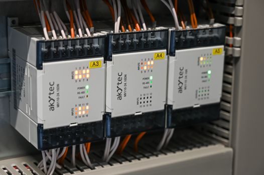
Option A — Zener IS barrier: passive shunt-diode network, 28 V typical, low cost, needs dedicated IS ground. Best for 4-20 mA loops entering MCCs that sit within 5 m of a Zone 1 boundary; not for motor feeders [S3]. Option B — Galvanic IS isolator: 3-way isolation, no IS ground required, higher accuracy, DIN-rail mount. Best for RTD/TC loops and PLC analogue inputs where ground-loop noise is a problem; still limited to the <1.3 W IS energy ceiling [S3]. Option C — Fuse inter-phase barrier + finger-safe terminal block: passive mechanical insulation, no energy limit. Best for motor starter buckets and any 480/600 V branch per IEEE 1683 spec language [S2]. Option D — XP/Ex e motor enclosure, no IS barrier at the MCC: required for motors in Zone 1, with the MCC located outside the classified boundary serving them with standard wiring [S3].
Spec gate the choice with three checks: (1) does the signal sit below 1.3 W / 30 V / 100 mA? (2) does the panel sit outside the 5 m classified boundary? (3) is field wiring 50 mm segregated, blue-jacketed, and IS-grounded below 5 Ω? Fail any check and the wrong barrier is in play.
Who Should NOT Pick a Generic IS Barrier
Defaulting to an off-the-shelf zener barrier on every MCC project is the most expensive mistake. An MCC bucket feeding a 75 kW motor at 400 V cannot use IS protection — the energy requirement alone is over 50× the IS ceiling, and the safety concept must shift to XP/Ex e motor certification plus an MCC outside the classified boundary [S3].
Likewise, a Zone 2 cabinet that is mechanically well sealed and sits in open air more than 5 m from any conduit entry does not need IS barriers at its terminals at all; the 5 m boundary rule eliminates them on siting alone [S3]. The fit-for-purpose check is energy level first, zone second, siting third — in that order.
Standards, Wiring, and the IEEE 1683 Spec Hook
IEEE 1683 (released 2014) is a guide, not a standard — it cannot be cited as a satisfied standard in the MCC specification, but its design recommendations (insulated fuse covers, finger-safe terminal blocks, multifunction digital overload relays, absence-of-voltage verification before bucket access) are legitimate spec lines [S2].
Layer the wiring rules on top: IS field cables must follow IEC 60079-14 segregation, blue-jacket identification, and low-impedance IS ground, and motor circuits must follow IEC 60079-7 for Ex e construction if the motor is inside the classified area [S3]. Engineers integrating the MCC into a control panel should also confirm wiring duct segregation and control cable ratings line up with the same 50 mm rule.
Shortlist Logic for 2026 Sourcing
Use this four-step filter on every line item: (1) is it a signal loop under 1.3 W → go to IS barrier or isolator; (2) is it a motor power branch → drop IS, specify XP/Ex e motor + IEEE 1683 bucket features [S2][S3]; (3) where does the panel sit vs the 5 m classified boundary → confirm with the Area Classification Drawing before specifying barrier count [S3]; (4) IEC 60079-14 field wiring compliance → 50 mm segregation, blue jacket, IS ground below 5 Ω [S3].
Trackable signals to watch in the next sourcing cycle: revisions to IEC 60079-14 installation clauses for IS field wiring, any updates to IEEE 1683 spec language on inter-phase barriers, and vendor releases of combined IS-barrier + signal-isolator modules that collapse the field-side wiring count for MCC-adjacent PLCs. For a broader LV motor-branch view, see the fuse vs MCC selection map.
Component reference pages worth checking: safety barrier, mcc cabinet, and safety fence.