A safety relay output contact can drive a 24 V DC PLC digital input at 5-15 mA across short panel wiring, and this is the most common pattern in modern control cabinets [S2][S5].
The constraint is not voltage, it is current: when the load falls below the relay's minimum contact current rating (often quoted around 5-10 mA for small signal relays), silver-alloy contacts can develop a high-resistance film and fail to conduct, a failure mode called contact wetting [S4].
Why a safety relay output is the right source for a PLC input
The consensus across 2017-2026 panel practice is to hard-wire the safety relay's redundant output contacts directly to the actuator (drive STO, contactor coil, valve) and tap a separate status contact into the PLC for HMI, alarm logging, and reset logic [S2][S5]. The PLC input is treated as a non-safe mirror; the safety function is complete the moment the safety relay de-energises, regardless of what the PLC does with the signal [S1].
Gene Bond on PLCTalk described the canonical 2017 pattern that is still quoted in 2026 designs: a separate hard-wired safety circuit, with one auxiliary contact from the safety relay feeding a PLC input for monitoring and alarm [S2]. On control.com the same thread reaches the same conclusion, the safety relay output must hard-wire to the drive enable and only a status copy goes to the PLC, and a DeviceNet or non-safety bus is not acceptable as the primary safety path [S5].
Electrical thresholds: minimum contact current and PLC input current
Most 24 V DC PLC digital inputs (Mitsubishi ALPHA 2, Allen-Bradley MicroLogix, Siemens S7-200, AutomationDirect CLICK) draw 5-15 mA at the ON threshold, with a rated input voltage of 24 V DC and a typical ON threshold of 15 V [S2][S3]. That range sits comfortably above the 5-10 mA minimum wetting current of most general-purpose safety relays, but it sits below the minimum rating of some legacy or reed-based relays, which is where field failures appear [S4].
plcprogramming.io's July 2026 reference frames the underlying physics with a worked example: the relay coil de-energises, the coil current drops to zero, the logic circuit reads "open," but the welded contact is still passing current, which is why monitoring contacts are redundant and force-guided, not relied on for the safety function [S4]. For the low-current direction, the same physics applies in reverse: an unwetted contact reads open electrically even though mechanically closed, producing a false "safety tripped" indication in the PLC.
Comparison: three ways to bring safety status into the PLC

The 2026 DigiKey system-level comparison, authored 14 April 2026, lines up the practical options for SIL/PL implementation against four decision criteria: wiring complexity, configuration method, diagnostic granularity, and the parts count of safety-rated hardware [S3].
For cabinet builders retrofitting 2-10 E-stops and door switches on a single machine, Option B remains the dominant 2026 pattern because the safety relay carries the SIL/PL rating and the conventional PLC handles sequencing without bearing any safety burden [S2][S3].
Wiring rules that decide whether the contact actually switches
Keep the safety relay output contact loop to the PLC input under 10 m of shielded twisted pair, drain grounded at the panel end, to keep loop impedance low and noise pickup out of the high-impedance PLC input [S5]. Verify the relay's datasheet minimum contact current; if the PLC input draws less than that value at the ON threshold, fit a 1-2 kΩ bleeder resistor across the input to lift the wetting current, or use a relay with a lower minimum rating [S4].
Fit a flyback diode only on DC coils (1N4007 or equivalent, cathode to +24 V) and never share a 24 V common between the safety relay output loop and any inductive load that could back-EMF the input [S5]. Where multiple guard-door switches feed one safety relay, series-wire the NC contacts and tap a second set for individual PLC monitoring if the safety relay has enough auxiliary outputs; this gives HMI per-door diagnostics without adding safety hardware [S6].
Failure modes the PLC input does NOT cover
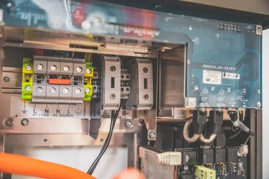
A PLC input wired to a safety relay's auxiliary contact cannot detect a welded main contact, which is exactly the failure the safety relay's internal redundancy and force-guided contacts are designed to catch, and which the PLC will never see because the welded contact continues to energise the load [S4]. The PLC also cannot stop the machine: the response time of a scan cycle (typically 5-50 ms) plus network latency is far longer than the safety relay's 10-25 ms drop-out time, which is why the safety-rated output must go straight to the contactor or drive STO input [S3][S5].
For a safety PLC implementation, the F-modules perform internal cross-check between redundant inputs and between redundant outputs at each scan; the conventional PLC input path cannot replicate that diagnostic depth, and field wiring faults (open, short, cross to 24 V or 0 V) are detected by the F-module's clocked test pulses rather than by the PLC input filter [S3].
Sourcing and standards
Engineers specifying this interface should anchor the design to the safety relay's SIL and PL ratings from its vendor datasheet, then verify that the PLC input current at the ON threshold sits above the relay's minimum contact current [S3][S4]. The risk assessment that determines whether a safety relay is even required, and at what category / PL, is the gating step before any wiring choice is locked in, and that step belongs in the machine's technical file rather than in the panel layout [S5].
Trackable signals to watch: vendor datasheets moving to publish minimum wetting current as a separately specified parameter (not buried in the "min. switching load" footnote) and PLC vendors offering a documented 24 V DC input with guaranteed current draw above 10 mA so the interface is unambiguous. Panel builders should also confirm whether their preferred safety relay's auxiliary contact is force-guided, since only force-guided contacts are guaranteed to be in a defined state when the main contact welds [S4].
Related analysis: Roller Chain Selection for Marine Drives: Pitch, Material, Service Factor.