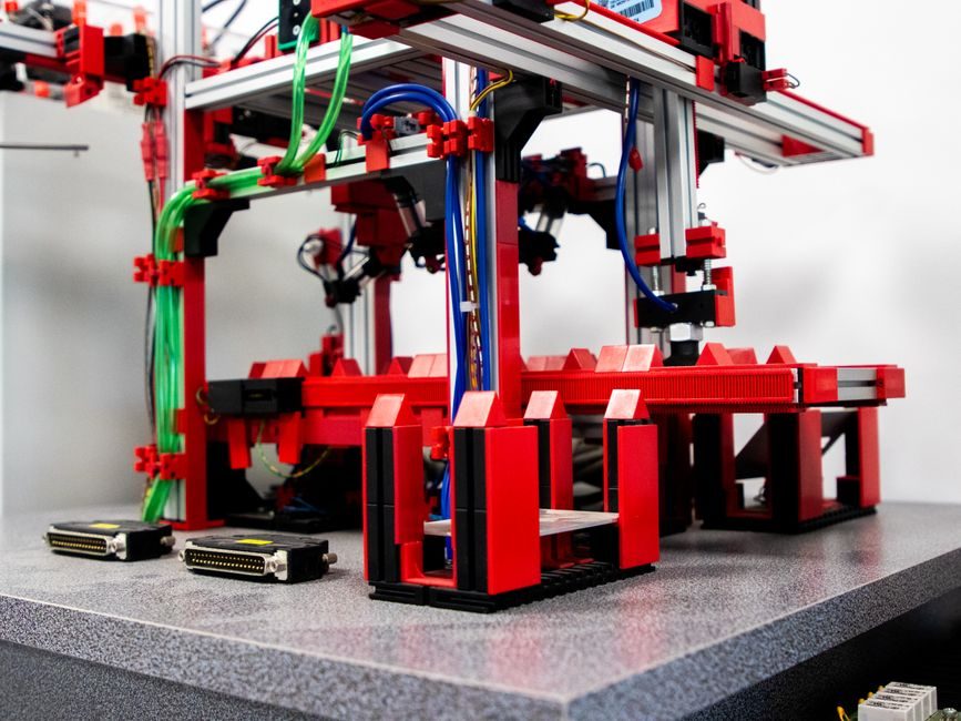
Safety relay selection in 2026 still comes down to four hard inputs: the target Safety Integrity Level (SIL per IEC 61508 / PL per ISO 13849-1), the output contact rating in amps and voltage, the input-device list, and the wiring architecture (single-channel, dual-channel equivalent, or dual-channel OSSD) [S1][S3].
The product family on the Sentry line from ABB covers basic, timer and expansion models, and the page groups them by application class — E-stop, light curtain, two-hand control, gate switch, muting, expansion I/O [S1]. Wieland's safety switching devices are documented to monitor E-stop buttons, light curtains, limit switches, magnetic switches, two-hand buttons and similar safety sensors [S3]. AutomationDirect's safety relay modules catalog organises the line by the same functional families plus an expansion backplane option [S4].
Start with the integrity level and the input device
The first citable assertion in any spec is the Safety Integrity Level or Performance Level the machine risk assessment demands — PLa through PLe per ISO 13849-1, or SIL 1 through SIL 3 per IEC 61508. The safety relay must be approved to that level; a device rated PLe / SIL 3 will also satisfy lower levels, but a SIL 1 device cannot be used where PLe is required [S1].
The second hard input is the sensor list. ABB Sentry models are categorised by what they accept at the input: E-stop / guard-door switches, light curtains with OSSD outputs, two-hand control stations, and muting applications [S1]. Wieland documents the same input families: E-stop, light grid, limit switch, magnetic switch, two-hand button [S3]. A relay that is rated for electromechanical E-stop inputs may not accept the pulsed OSSD outputs of an ESPE Type 4 light curtain without an explicit OSSD-compatible model — the input circuit must match the sensor technology in writing.
Channel architecture: 1-ch, 2-ch equivalent, 2-ch OSSD
Channel architecture is the next decisive criterion. Single-channel (1-ch) wiring is the lowest-cost option and is only acceptable where the risk assessment permits a single fault-tolerant input path; it is rare on new European machinery. Dual-channel equivalent (both channels switch on the same input device contact pair) is the common default for E-stop and guard-door monitoring [S3].
Dual-channel OSSD is mandatory for electrosensitive protective equipment such as Type 4 safety light curtains — both OSSD outputs must pulse and be cross-fault monitored by the relay, typically within a 20 ms discrepancy window. The same wiring family applies to safety mats monitored by a short-circuit detecting input. When specifying, the datasheet must list "OSSD" or "pulsed short-circuit detection" explicitly; a generic "PLe dual-channel" claim without that text is not sufficient. For a deeper dive into light-curtain resolution, safety distance and OSSD pairing, see the Type 4 safety light curtain 2026 selection guide.
Contact rating, utilisation category and electrical life
Output contact rating is the most-fudged number on a safety relay datasheet. Two values must be checked: the thermal continuous current (Ith) and the utilisation-category rating (AC-15 / DC-13 in IEC 60947-5-1 terms) at the working voltage. A relay rated 6 A Ith may only be approved for, example, 2 A at 250 V AC under AC-15 and 1 A at 24 V DC under DC-13 — those are the numbers that count when switching contactors or solenoid valves, not the headline 6 A [S1].
Electrical endurance is the second rating most engineers miss. Safety relay contacts that switch a contactor coil every machine cycle are wear parts; the datasheet should state a mechanical and an electrical life curve, e.g. "10 million mechanical / 100,000 cycles at AC-15 2 A / 250 V". Below that, the safety outputs (red terminals) and the auxiliary/signalling outputs (yellow/green) are usually separately rated — auxiliary contacts often run 100 mA to 1 A only, so wiring a contactor coil to an auxiliary terminal is a common field failure. The safety relay encyclopedia entry summarises the contact-rating conventions.
Response time, test pulse and cross-fault monitoring
Response time and the diagnostic test pulse are two numbers that affect the safety distance calculation. The relay's input filter, cross-fault check and output turn-off time add directly to the stop time in the formula s = K·(t_device + t_relay + t_machine) + C, where t_relay is the safety relay's worst-case response time, typically 10–25 ms for electromechanical safety relays and 5–15 ms for solid-state or electronic safety relays [S1].
The test pulse behaviour on a 24 V DC input is the third trap. Many electronic safety relays inject a short OFF pulse (typically 0.5–2 ms) on the input to detect cross-wiring and stuck contacts. That pulse is invisible to an electromechanical contact, but some older safety mats and interlocks can drop out on it. The datasheet must be checked for "test pulse length" and "pulse rejection by input device" before the relay is paired with a non-standard sensor. A reusable gaging concept for these timings is captured in the safety relay module reference.
Wiring topology: fixed terminals, pluggable, push-in

Terminal style decides service time, not safety integrity. Screw terminals remain the lowest-cost option and are still standard on most general-purpose safety relays [S1]. Pluggable terminal blocks (often with coding pins) allow the wiring harness to be pre-built and the relay replaced in seconds — the typical fit for control cabinets that are serviced frequently.
Push-in (direct-insert) terminals are now common on Sentry and Wieland lines and cut wiring time on 24 V DC control circuits where ferrules are used; they are not a substitute for screw terminals where vibration or large conductors are present. The terminal style does not change the SIL/PL rating, but the maximum conductor cross-section (e.g. 0.2–2.5 mm² for control wiring, 0.5–4 mm² for power) does, and that figure is often buried in the datasheet. Power-supply wiring (24 V DC vs 110–230 V AC) is a separate decision: AC-powered units need a neutral conductor and an external fuse, DC-powered units run on the same 24 V DC bus as the rest of the I/O, which is the common modern architecture for safety relay modules in a PLC cabinet.
Comparison of the three common safety relay classes
Across the three functional classes sold by major lines [S1][S3][S4], the trade-off is fixed:
• Basic (single-function) E-stop / guard-door relay — narrowest function set, lowest cost, typical PLe / SIL 3 on dual-channel, response time 10–25 ms, fixed screw terminals, 2 or 3 safety NO + 1 NC auxiliary. The right choice where the machine has one safety function and the panel is small. Not the right choice where muting, time delay or expansion is required.
• Configurable / timer / expansion relay — selectable input mode (E-stop vs OSSD vs two-hand), on-board time delay (0.1–30 s) for category-1 stop functions, modular expansion I/O via a side bus. Typical use: cell with light curtain, two-hand station and a delayed E-stop for a guard door. PLe / SIL 3 across all modes, response time 15–30 ms, pluggable or push-in terminals.
• Solid-state / contact-expansion safety relay — zero-contact output for high-cycle applications, or a contact-multiplier module that takes one safety input and drives several downstream contactor banks. Long electrical life (no contact wear), but a hard requirement on short-circuit protection of the output (typically a 4 A fast-blow fuse) that is often left out of the panel design.
For most cabinet builds the middle class is the default; the basic class is for one-function cells; the solid-state / expansion class is for high-cycle or high-output-count machines.
Use cases, failure modes and what to avoid

The standard use cases a safety relay will be paired with — E-stop, guard door with interlock switch, Type 4 light curtain, two-hand control, muting, hold-to-run — map one-to-one to the model families in the Sentry catalogue and to Wieland's sensor list [S1][S3]. The AutomationDirect safety relay modules page segments the same families and adds an expansion backplane for systems that need more than four safety functions [S4].
The recurring field failure modes are: (1) wiring an auxiliary NC contact to a contactor coil, (2) using a 1-ch wiring scheme on a PLe risk that requires 2-ch, (3) ignoring the test pulse and getting a safety mat that latches off at power-up, (4) exceeding the utilisation-category rating on a 24 V DC inductive load, and (5) forgetting that the safety relay's response time must be added to the safety-distance calculation of any light curtain. Reference reading on the related sensor wiring is summarised in the Type 4 light curtain 2026 guide.
For cabinet layout, the safety relay sits between the sensor field wiring and the contactor / drive STO input. The signal flow is: sensor → safety relay inputs → safety relay outputs → (a) contactor coil or (b) STO input of a VFD/servo, with the auxiliary NC used to feed a PLC status word. Any variation of that signal flow needs to be justified in the risk assessment file. The physical placement — inside the same cabinet as the contactors, on a DIN rail next to the PLC, or in a separate safety panel — is driven by the EMC environment and the number of safety functions; a panel with more than eight safety functions is usually better served by a safety PLC than a stack of safety relays.
Standards, sourcing and what to pin in the spec
The standards a safety relay must be approved to are governed by the application, not by the brand. Generic approvals to look for: EN ISO 13849-1 (PL), IEC 61508 / IEC 62061 (SIL), UL 508 (North America), and CCC for the China market. For hazardous-area mounting near an Ex-protected enclosure, the relay is normally installed inside a non-Ex cabinet, with the field wiring entering through safety barriers — the safety relay itself is not an Ex device. [S1]
On the Sentry line the approvals are listed on the product page and on the datasheet for each variant; the same is true for Wieland and for AutomationDirect's safety relay modules [S1][S3][S4]. On the BOM, pin the following: PL/SIL rating with the exact number (not "PLe-compatible"), input-mode list, output contact rating in utilisation-category form (AC-15 / DC-13) and at the actual working voltage, response time, test-pulse behaviour, terminal style, and approvals list. Everything else — including brand — is decided after those numbers are fixed.
Trackable next node: verify the safety relay's input filter / test-pulse behaviour against the specific sensor datasheet before release of the panel drawing, and add the relay's worst-case response time to the safety-distance calculation in the light-curtain risk-assessment sheet.
For component-level specifications, see safety fence.