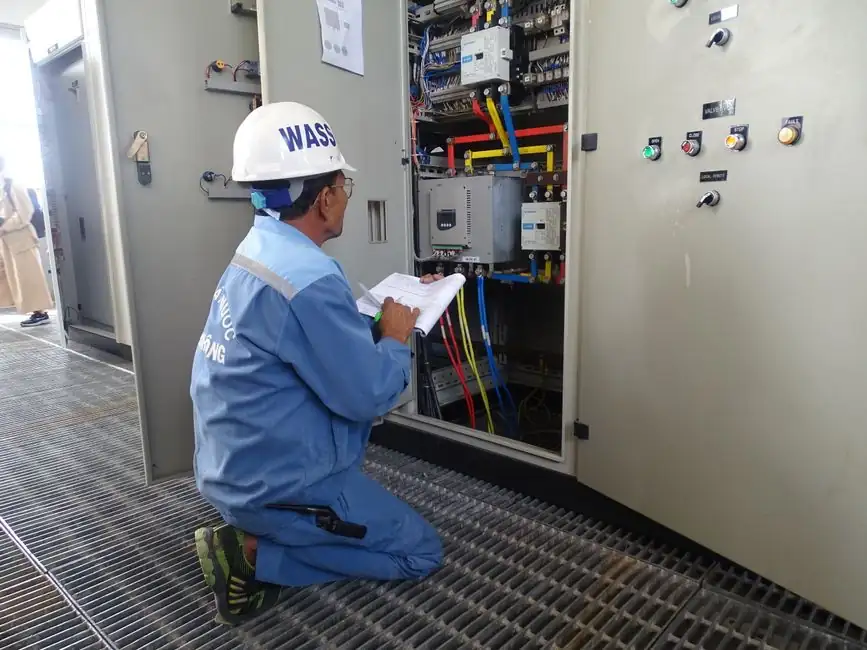
A sander inspection checklist groups checks into machine condition, operating environment, and supervision, with pre-start acceptance values that include a 36-inch (914 mm) clearance in front of any disconnecting means for safe maintenance [S2]. On disc sanders, the work table must be adjusted to within 1/4 inch of the disc at every point of contact to minimise the gap at the nip point [S2]. The abrasive belt or disc must be enclosed by guarding except at the working face, and sanding belts must be installed for the correct direction of travel [S1].
For general workshop use, SafeWork NSW treats the checklist as a structured audit covering stability, push pads for stroke sanders, controls labelling, emergency stops, isolation, dust extraction, lighting, and PPE issuance, with the operator signature recorded against each shift inspection [S1]. Australian and California frameworks differ in citation language but converge on the same engineering targets: stable mounting, guarded nip points, accessible mushroom-head E-stop, isolation, and dust control [S1][S2].
Machine stability, abrasive media, and push-pad availability
Stability is the first line of defence: the sander must be securely restrained to prevent movement, either by the OEM mounting pattern or by sound engineering practice, per 8 CCR §3328(d) [S2]. For belt and disc sanders, the abrasive must run inside a guard that encloses every nip point, including the belt-to-pulley interface on belt machines and the full periphery of the disc on disc machines [S1][S2]. On stroke sanders, a push pad must be available and used; hand-held workpieces against a moving abrasive are a common citation cause [S1].
Acceptance values for the abrasive itself are quantitative: the sanding belt must be tracked for the correct rotation arrow, tensioned to OEM spec (typically a 0.5-1.0 inch deflection at mid-span under moderate finger pressure for a 4-inch-wide belt, though OEM data sheets govern), and free of frayed edges, burn marks, or exposed splice joints [S3]. The disc must be free of grooves deeper than roughly 1/32 inch, concentric within 0.005 inch runout at the periphery, and the table gap must hold under load, not just statically [S2][S3].
Controls, emergency stop, and lockout/tagout
Operating controls must be within easy reach, marked for function, and designed to prevent accidental start-up, with stop/start buttons, E-stops, and safety bars all verified to operate effectively before the shift starts [S1]. The emergency stop must be the mushroom-head type, or an equivalent palm-operated device, and must be clearly labelled and unobstructed [S1]. On installations with hard-wired supplies, the disconnecting means must be immediately adjacent to the machine and legibly marked to identify the equipment it isolates, per 24 CCR 3 §110.22 / NFPA 79 §5.1.9.2 [S2].
For maintenance and jam-clearance, a written and verified Hazardous Energy Control procedure (Lock Out Tag Out, LOTO) must be readily available at the machine, per 8 CCR §3314(G), and lockout/danger tags must be applied before any guard removal, belt change, or dust-collector service [S2][S3]. A related pre-use angle-grinder workflow uses similar LOTO sequencing, as laid out in the Angle Grinder Inspection Checklist, where pre-use, in-service, and post-use checks all route back to the same isolation point.
Electrical supply, clearances, and signage

Hard-wired sanders must be supplied from a branch circuit rated for at least 125% of the machine's full-load current, per 24 CCR 3 §670.4(A), with the attachment plug either connected directly to the building wiring or terminated at an adjacent disconnect [S2]. The power cord and plug must be free of cuts and insulation fraying, per 8 CCR §3328(c), and routed so it cannot become a tripping hazard at the operator station, per 8 CCR §3273(a) [S2]. A minimum 36-inch (914 mm) working clearance in front of the disconnect is mandatory for safe maintenance access, per 24 CCR 3 §110.26 [S2].
Enclosures around live parts must carry a safety sign in accordance with ANSI Z535.4 warning qualified persons of electric-shock and arc-flash hazards, per 24 CCR 3 §110.16 / NFPA 70E §130.5(H) [S2]. Voltage and phase must be recorded on the checklist: typical single-phase hobby machines are 120 V, while industrial three-phase disc and wide-belt sanders run 208 V, 230 V, 380 V, 400 V, or 480 V depending on the regional grid, and the form should force the inspector to tick 1-phase or 3-phase before the machine is energised [S2].
Guarding geometry and nip-point control
Belt sander guards must prevent finger contact with the nip point formed between the sanding belt and each pulley, with the guard wrapping the pulleys to within OEM-specified distance of the belt (commonly 0.25 inch or less at the closest point), per 8 CCR §4312 [S2]. Disc sander guards must wrap the full periphery of the disc and leave only the working face exposed, per 8 CCR §4313, while belt and pulley power-transmission parts must be guarded to 8 CCR §4070 [S2]. The disc-table gap acceptance value is set at 1/4 inch maximum at every point, which is the most-cited violation during shop audits [S2].
Where guarding is adjusted for a specific operation, the adjustment must be the minimum necessary, and a positive locking method (not friction alone) must hold the guard in place, mirroring the rules in the related Angle Grinder Safety: PPE, Wheel Checks, and Guard Rules guidance. If the guard cannot be set within the OEM envelope, the machine must be tagged out and the guard replaced, not bent or shimmed, before work resumes [S1][S2].
Dust extraction, noise, and industrial hygiene

Wood-dust extraction is not optional: the system must be correctly fitted, switched on during operating hours, and maintained to keep airborne combustible dust below hazardous thresholds, with the collector ducted outside or to a recognised filtration receiver [S1]. A noise survey must be performed while the sander is running in normal operation, per 8 CCR §5097(b), and sound-absorbing material or isolation mounts should be considered where readings exceed the workshop action level (commonly 85 dBA over an 8-hour LEX,8h exposure, though local rules govern) [S1][S2].
Housekeeping closes the loop: the floor around the sander must be cleaned regularly, off-cuts and dust sweepings removed, and the floor surface must provide a safe, firm foothold, since wood dust mixed with coolant or oil becomes a slip hazard within minutes of being generated [S1]. The cord routing, dust hose, and compressed-air lines must all be kept clear of the operator's foot zone, and the work area must be lit with task lighting that is itself protected against impact from ejected workpieces [S1].
Operator training, PPE, and supervision
Operators must be trained, experienced, and supervised by a competent person during any training period, with the supervisor's signature attached to the inspection record alongside the machine ID, inspection date, and assessor name [S1][S2]. PPE issuance must match the task: safety glasses with side shields (Z87.1-rated), hearing protection to the surveyed noise level, dust mask or respirator selected for the wood-dust exposure, and no loose clothing, gloves, or jewellery near rotating spindles or belts [S1][S3].
Gloves are explicitly excluded for most sander work because they can catch on rotating spindles and pull the hand into the nip point, an exclusion that mirrors the Angle Grinder Lifespan: When to Service, When to Scrap guidance on bare-hand proximity to rotating abrasives. Where a stroke sander or a polishing head is used, a push pad or jig must substitute for the gloved hand, and the inspection checklist should record its presence before each shift [S1].
Decision rules: when to pass, when to tag out

A sander passes pre-use inspection when all installation, safeguarding, electrical, hygiene, and housekeeping items on the checklist are marked YES or N/A, with any NO item carrying a documented correction date [S2]. The machine is tagged out and removed from service if the disc-table gap exceeds 1/4 inch, the belt guard is missing or fails to prevent nip-point contact, the E-stop does not latch, the disconnect is not labelled, or the dust collector is inoperable during sanding [S1][S2].
Trackable signals to watch between audits: a rising count of "NO" answers in the same checklist section (typically guarding or dust) indicates systemic drift and a training or design-control failure rather than isolated operator error; and a fall in noise-survey dB after a hood or extraction change is a leading indicator that the dust and acoustic load has actually shifted, not just the paperwork. For procurement teams comparing sanders, treat the checklist as the acceptance test: any machine that cannot pass all YES/N/A items on a quiet bench trial is not a candidate for site acceptance, regardless of OEM reputation. Detailed mechanical pre-start routines for adjacent equipment are covered in the Bulldozer Pre-Operation Inspection Checklist, which uses the same closed-out YES/NO discipline with measured acceptance values.
For the relevant spec sheets and selection criteria, see sander, pressure transmitter, and flow meter.