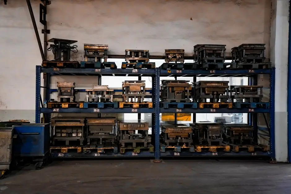
Foundries specifying shell molding lines for fluid-handling components typically run flask capacities between 500×500 mm and 600×600 mm, with pattern plates spanning 15×20″ up to 30×44″ for the largest valve and pump bodies [S1][S3].
For pump and valve work, the line must handle thin-wall sections, complex internal flow paths, and alloys ranging from carbon steel to stainless and high-temperature superalloys, while keeping cycle times short enough to justify mid-to-high volume runs [S2]. The equipment choices below break down the criteria that actually move a procurement decision, from flask size and shoot orientation to material compatibility and integration with secondary processes.
Flask Size and Pattern Plate Range
Flask capacity is the first hard gate in shell molding machine selection: the envelope must clear the largest pump casing or valve body in the planned mix, with margin for parting line, feeders, and gating. Operating fleets documented in 2026 commonly include machines at 500×500 mm, 500×600 mm, and 600×600 mm, with dump-box mould makers at 600×600 mm and 600×450 mm for matched-pair shell assembly [S3]. At the upper end, pattern plates sized 30×44″ support large valve bodies and multi-cavity layouts, while 15×20″ and 20×30″ plates cover the bulk of mid-range pump impellers, bonnets, and small valve casings [S1]. A useful rule is to size the flask 10–15% larger than the largest part, so risers and core prints do not crowd the box edge.
Horizontal shell core shooters dominate high-volume core production, with one Indian foundry running 28 horizontal units and just 2 vertical units, a ratio that reflects cycle-time economics on repeatable valve and pump cores [S3]. Vertical shooters tend to be reserved for deeper, more intricate cores where drop orientation matters more than throughput.
Process Definition and Equipment Stack
A complete shell molding line pairs a shell molding machine with a shell core machine, a shell mould fuser, and an automated dump-box mould maker; resin-coated sand is dropped onto a heated metal pattern, cured into a rigid thin-walled shell, then stripped, clamped, and poured [S2][S3]. The same facility stack typically includes automated sand processing and in-house tooling, which compresses lead time and keeps shell thickness consistent across batches [S1].
For foundries that also serve aerospace or precision instrument customers, the shell line is often integrated with colloidal silica investment casting so the same metallurgy lab and finishing cell can move parts between processes [S2]. This dual-process layout is a practical answer to the perennial shell-vs-investment question: shell molding wins on cycle time and unit cost for medium-sized components, while investment casting wins on surface fidelity for ultra-intricate valve internals.
Material Compatibility for Pump and Valve Alloys
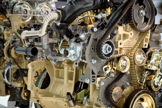
Shell molding is fully compatible with stainless steel, carbon steel, low-alloy steels, high-temperature superalloys, and non-ferrous metals, which covers the full pump-and-valve material matrix from 304/316 stainless to nickel-base alloys used in corrosive service [S2]. Investment casting, used as a benchmark for surface finish on valve bodies, bonnets, and discs, accepts the same family plus brass and bronze [S4]. For foundries running both stainless and carbon-steel valve lines on a single shell machine, pattern plate temperature control and resin formulation become the two levers that prevent shell-mould fusion defects when switching alloys.
Common parts produced by shell moulding for fluid handling include pump bodies, impellers, gear housings, and valve casings, all of which benefit from the smoother surface that reduces post-cast machining [S3]. Where valve components see high pressure, high temperature, or corrosive media, the casting method must support both design accuracy and material performance, a criterion that maps directly onto shell molding's combination of thin-wall reproduction and structural density [S4].
Shell Molding vs Investment Casting for Valves
Three decision criteria separate the two processes on a real procurement: surface finish, dimensional tolerance, and per-unit cost at volume. Shell molding delivers faster cycle times and lower tooling cost for medium-sized parts with thin walls and complex internal geometries, while investment casting is unmatched for ultra-intricate configurations and the smoothest sealing surfaces [S2]. Investment-cast valve components typically require additional grinding, polishing, heat treatment, machining, and inspection to reach the required surface finish and dimensional stability for high-pressure service [S4].
For pump and valve buyers cross-shopping the two, a practical decision is: choose investment casting for small bonnets, discs, and seat rings where surface finish and tolerance dominate; choose shell molding for pump casings, large valve bodies, and manifolds where throughput, structural ribs, and uniform thin walls matter more than mirror-finish sealing faces [S2][S4]. A complementary read on ball valve advantages, limitations, and selection criteria helps translate casting-process choice into end-component performance, since ball valves place the heaviest demands on sealing-surface finish.
Surface Finish, Tolerances, and Machining Allowance
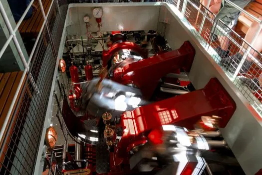
The fine sand and resin mixture used in shell moulding produces smoother cast surfaces than conventional green sand, which directly reduces secondary machining and polishing on pump impellers and valve bodies [S3]. Industry guidance on precision shell moulding emphasizes three advantages for fluid-handling parts: accurate reproduction of intricate designs, sharp corners, and thin sections; a smoother as-cast surface that cuts post-machining; and repeatability that supports high-volume runs without dimensional drift [S3].
Where tighter tolerances or smoother sealing faces are required, integrating the shell line with investment casting lets the foundry route specific features (such as a valve seat or disc face) to investment while keeping the main body on the shell line, a hybrid flow that the Vastmaterial documentation describes as a balanced manufacturing flow optimizing unit cost and surface finish together [S2]. For foundries scaling up, a machine tool procurement strategy built around spec-matched selection keeps the post-cast machining cell aligned with the as-cast tolerance band coming off the shell line.
Cycle Time, Lead Time, and Production Economics
Shell moulding is well-suited to high-volume manufacturing because of its repeatability and reduced cycle times, which is why it is widely specified for pump and valve bodies where batch sizes justify dedicated flask tools [S3]. Quoted lead times for precision cast pump and valve components in the 2026 sourcing landscape run from as little as 10 days on digital investment-casting routes to longer cycles on conventional shell lines, with unit costs tied directly to flask utilization and shell-thickness consistency [S5]. Equipment choices that move the economics include fully automated horizontal core shooters for repeatable valve cores, automated dump-box mould makers for consistent shell halves, and shell mould fusers that lock dimensional accuracy before pouring [S3].
Buyers evaluating a new shell line should track two verifiable signals: the foundry's published flask-capacity matrix (500×500 mm up to 600×600 mm is the current fluid-handling norm) and the ratio of horizontal-to-vertical core shooters, since a high horizontal count correlates with the cycle-time profile that mid-volume pump and valve production needs [S3]. Where aerospace-grade castings share the same shop, comparing this selection guide against a shell molding machine spec map for aerospace castings clarifies which flask sizes and tolerance bands to reserve for fluid-handling work.
Track these nodes through 2026: published flask-capacity data from additional Indian and US shell foundries, and any 2026-Q3 updates to in-house tooling and automated sand-processing lines at North American precision shell moulders, both of which directly affect pump and valve line capacity.