
A standard single girder overhead crane is built around one load-bearing bridge beam, end trucks on each runway, and a hoist that is most commonly underhung on the bottom flange of that beam [S1].
That one-beam architecture is what defines the capacity ceiling. Published design guides converge on a 15 to 20 ton sweet spot for off-the-shelf units, with custom builds documented up to 32 to 35 tons before structural and hoist geometry penalties dominate [S2][S3][S4].
What "Capacity Ceiling" Actually Means on a Single Girder
Single girder capacity is a coupled limit, not a single number: as rated tonnage climbs, maximum permissible span drops in a near-linear trade-off because the rolled I-beam and monobox sections commercially available cannot grow in stiffness without growing in self-weight [S2].
The cost-effective envelope table widely used by U.S. integrators ties 7.5 tons to 80 ft of span, 15 tons to 65 ft, 25 tons to 55 ft, and 35 tons to 45 ft, with a 20 ton / 60 ft pair sitting in the middle as the most quoted point [S2]. Above roughly 15 tons and 65 ft, the same reference flags a double girder crane as the more practical solution [S2]. The dominant commercial Chinese builder references a 31.5 m span and 32 ton rated capacity as the practical single-girder envelope in standard configurations, beyond which girder deflection rules out continued use of a single rolled section [S4].
What the Research Shows Across Multiple Sources
Surveying the spec literature, three clusters of consensus emerge on single girder crane capacity. Sources quoting the conservative envelope list 1 to 20 tons for light and medium duty, with 5 to 20 tons as the most common production range [S5][S6][S7][S8]. Mid-range sources peg the practical ceiling at 15 tons for general industrial work and note that single girder units "will rarely" be rated higher than 15 tons in standard CMAA Class A through C service [S1][S2]. High-end sources document engineered single girder packages up to 32 to 35 tons, explicitly framed as "standard up to 35 tons" with "higher available" on custom order, and 31.5 m / 32 ton as the practical upper bound before girder sizing forces a topology change [S3][S4].
The variance tracks with duty cycle classification, not just capacity. CMAA Class A (standby) through Class C (moderate service, 5 to 10 lifts per hour at 50% of rated load) is where single girder cranes are competitive on cost per ton [S3]. Class D (heavy service, 10 to 20 lifts per hour, not more than 65% at rated load) and above push designers toward double girder regardless of the headline tonnage [S3]. For a single girder crane selection, the right question is not "how high can capacity go" but "what combination of tonnage, span, lift height, and CMAA class can be served by one rolled section without exceeding L/750 to L/1000 deflection limits."
Selection Criteria That Actually Move the Capacity Number

Four variables set the practical capacity ceiling on a single girder installation, and each is independently quantified in vendor literature. The first is span, defined as the center-to-center distance between runway rails rather than building width, with a planning rule of thumb of building column-center spacing minus 1.0 to 1.5 m [S4]. The second is duty cycle, with CMAA classifications A through F grading service from standby to continuous severe use at near-rated capacity [S1][S3]. The third is top-running versus under-running geometry, where underhung hoists save headroom at the cost of capacity headroom because the bottom flange carries the trolley rail. The fourth is hook approach and headroom, with required building headroom equal to lifting height needed plus hoist body height plus hook deadweight travel plus a top safety clearance of roughly 100 mm, and 700 to 1,000 mm of "lost" headroom is typical once every mechanical deduction is added [S4].
For applications where capacity is the dominant variable and span is moderate, the gantry crane and mobile crane categories offer higher single-unit ratings, but they trade away the building-mounted runway advantage that makes single girder units cheap to install in existing facilities. The single girder remains the right answer when the bay is fixed, headroom is constrained, and lift counts fall inside CMAA Class B or C.
Who a Single Girder Crane Is For, and Who It Is Not For
Single girder designs fit light to medium duty work where the most common lift stays below 50% of nameplate rating, typical of machine shops, sawmills, light fabrication, small-parts warehousing, and end-of-line packaging cells [S3][S5]. The economic case rests on three factors: less material in the bridge means lower purchase, freight, and install cost; lower deadweight means lighter runway structure and lower building foundation loads; and a single beam profile means faster install and easier service access [S1][S2].
Single girder is the wrong choice for heavy steel coil handling, paper mill reel moves, power plant turbine lifts, automotive stamping-die changes, and any service classified CMAA Class D or higher [S3]. The same applies to any application where span exceeds roughly 60 ft (18.3 m) at moderate capacity, because most rolled sections are not produced in lengths above 60 ft without a splice, and splices penalize stiffness exactly where the single-beam topology can least afford to lose it [S1]. Above 15 tons and 65 ft, or above 20 tons at any span, the cost-effectiveness case flips: a double girder crane of equal rating costs less in steel per ton lifted because the load is split between two beams and the hoist can be base-mounted on top of the rails, freeing hook approach on both sides [S2].
Comparison Against the Main Alternatives

Lining the three dominant bridge topologies against the four criteria that matter at the spec desk gives a clean decision matrix. On rated capacity, single girder tops out near 32 to 35 tons in engineered configurations, double girder scales to 100 tons and beyond, and top-running monobox reaches 200 tons or higher at industrial CMAA Class D through F [S3][S5]. On typical span, single girder holds the 31.5 m / 60 ft envelope, double girder routinely reaches 90 ft, and special bridge designs run to 150 ft [S2][S3]. On cost per ton in light to medium duty, single girder is the lowest, with double girder and monobox both carrying premium pricing for the additional steel and the higher-spec hoist. On headroom efficiency, single girder with an underhung trolley saves the most, because the hoist sits below the beam rather than mounted on top. The cost-effective design table referenced earlier is the cleanest way to read this trade-off: at 7.5 tons, span can be 80 ft; at 35 tons, span collapses to 45 ft, with each increment of capacity trading directly against reach [S2].
For a crawler crane or mobile crane serving outdoor or intermittent work, the same capacity bands exist but the headroom, building integration, and repeat-cycle efficiency cases are different. Inside a fixed bay, the decision rarely has anything to do with absolute tonnage and almost everything to do with span, duty cycle, and hook approach.
Limitations, Failure Modes, and Misconceptions
Three failure modes define where a single girder crane hits its practical wall. Girder deflection is the first, with typical serviceability limits in the L/750 to L/1000 range depending on standard; exceeding that bound on a single rolled section forces a deeper, heavier beam or a switch to double girder [S4]. Hoist mounting geometry is the second, because underhung hoists on the bottom flange cannot be larger than the flange width itself, and the biggest underhung hoists stall out around 20 tons in most product lines. End truck and runway wheel load is the third, because the entire lifted load passes through one beam into two end trucks, doubling the per-wheel load compared with a double girder of equal rating and forcing heavier runway beams and stronger building columns [S2].
The most common misconception is that single girder cranes are "lighter duty" or lower quality than double girder cranes; properly designed single girder units in CMAA Class A through C are not inferior, they are simply a different topology for a different duty profile [S2]. A second misconception is treating the published "up to 20 ton" or "up to 35 ton" number as universal; the actual capacity in any specific bay is governed by the span-versus-tonnage table, not by the headline tonnage on the brochure [S2]. A third misconception is that a crane scale retrofit changes capacity; it does not, because the load cell sits below the hook and only measures, it does not reinforce the bridge. Sources covering alternatives for related lifting work, such as rebar hook bending on a bender or pallet rack beam ratings, illustrate the same principle at smaller scale: capacity is a structural limit, not a measurement limit.
Sourcing and Standards
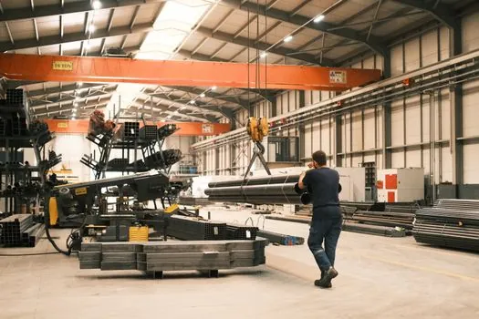
U.S. overhead crane duty classification is governed by the Crane Manufacturers Association of America (CMAA) six-tier system, Class A standby through Class F continuous severe service, with cycle and load percentage defined for each tier [S1][S3]. Design rules in the European and Chinese markets are typically built around FEM 1.001 and GB/T 3811, both of which are referenced in current OEM factory-layout design guidance [S4]. Headroom and clearance assumptions of roughly 100 mm per side between end beam and building structure, plus 700 to 1,000 mm of total lost headroom once all mechanical deductions are added, are standard in modern supplier guidance and trace back to those FEM and GB/T design rules [S4].
The 60 ft / 18.3 m rolled-section limit and the cost-effective design table pairing tonnage to span are stable engineering references documented across multiple OEM catalogs and integrator guides [S1][S2]. The 31.5 m / 32 ton single girder practical envelope is the most current OEM guidance published in mid-2026 [S4]. Any procurement decision that crosses the 15 to 20 ton band, the 60 ft span band, or the CMAA Class C / D boundary should be re-quoted as a double girder package rather than pushing a single girder topology past its working envelope.
Trackable signals to watch: published updates to CMAA 70 or 74 spec revisions that redefine the deflection limits at the L/750 to L/1000 boundary; OEM datasheet shifts in the 30-plus ton single girder segment as Chinese fabricators push the envelope with monobox girders; and revisions to FEM 1.001 or GB/T 3811 that change the headroom deductions in the 700 to 1,000 mm band, since those deductions directly eat into usable lifting height on any single girder installation [S4].