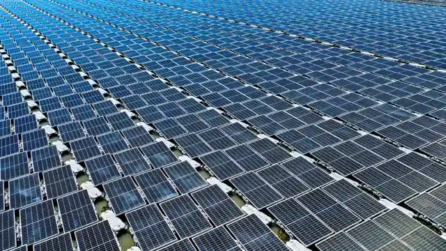
PV cell-line process control resolves into a four-node instrument stack: irradiance reference, cell/module electrical test, thermal profile, and lamination vacuum/pressure, each with its own calibration chain back to a recognised metrology institute [S5].
On the upstream furnace side, the same control discipline applies to horizontal batch diffusion (POCl3, BBr3) and PECVD (Si3N4 antireflective coating) systems, where 0.1 °C temperature control stability and ±3-5% on-wafer uniformity are the contract values engineers design against [S2].
Furnace Stack: Diffusion, PECVD, and Temperature Stability
Horizontal batch diffusion furnaces sized for 125 mm, 156 mm, and 210 mm pseudo-square wafers run 400 wafers per tube, with POCl3/BBr3 cycles averaging 60 minutes and a sheet resistance window of 40-160 Ω/□, per the SVCS SV SOL family data [S2].
The furnace temperature controller, an automatic unit on POCl3/BBr3 bubbler containers, holds +50/-20 °C relative to ambient with 0.1 °C control stability and a 2-hour maximum time-to-stabilise, which is what makes the sheet-resistance spec reproducible run to run [S2]. Gas delivery uses automatic/manual source cabinets (SiH4, NH3, B2H6, PH3, SiH2Cl2, H2, Ar, O2, N2O, N2) and VMBs feeding continuous flow from units to thousands of slm with automatic changeover to replenished source vessels [S2].
Continuous APCVD for 125 mm × 125 mm and 156 mm × 156 mm cells runs at 1500 WPH (156 mm format) on metal-addition-free SiC trays, with a deposition temperature around 430 °C and a film-thickness uniformity of ≤±10% on the AMAX1000S platform [S1]. Wafer transfer uses a high-speed double-arm mechanism with special wafer pockets, and heater coils plus lamp heating form the thermal stack [S1].
Inline Cell and Module Electrical Test
Three electrical nodes sit between cell coating, stringing, and final layup: IV curve tracing, electroluminescence (EL) imaging, and ground-fault/hipot testers, with EL defect resolution specified at 0.2 mm/pixel or finer for hot-spot detection on shingled cells [S5]. A common inline configuration pairs a four-wire Kelvin sense on the cell probe bar with a 1000 V/8 mA EL bias supply, and the test data is binned by Pmax and fill-factor so the stringer can grade cells into current-matched groups [S5].
For module-level sorting, a Class AAA flash tester (per IEC 60904-9 spectral match) closes the loop on nameplate wattage, while inline EL cameras sized for the SELA-V20.D5-class module tester footprint feed defect data into the rework decision [S3][S5]. Argus Solar's SELA-V20.D5 on-line EL appearance inspection machine is a representative piece of this stack: 900 kg unit, 271 × 213 × 132 cm, applied to crystalline silicon module validation [S3].
Thermal Loop on Tabber, Stringer, and Reflow
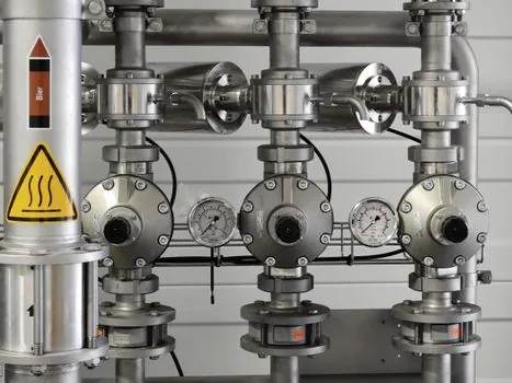
Tabber and stringer IR lamps hold solder-zone temperature in the 320-380 °C window for Sn60Pb40 and 340-420 °C for lead-free SAC305, with a K-type thermocouple bead on the cell busbar providing the closed-loop signal to the PID controller; the same thermocouple is dual-redundant in higher-yield lines [S5]. Profiling of the reflow belt typically uses a 6-to-8 channel K-type profile thermocouple, with ΔT across the cell kept under 5 °C to avoid micro-cracking [S5].
Transmitter heads in the HART or IO-Link protocol family let the same sensor land on either a legacy 4-20 mA DCS or a modern IO-Link master without rewiring, which is a real retrofit cost saver on brownfield PV lines [S5]. The cell and module loop downstream of the stringer is covered in more depth in the solar cell manufacturing equipment spec map.
Lamination Stack: Vacuum, Pressure, Encapsulant Cure
Laminator control is built around a heated-platen PID loop (setpoint 140-160 °C for EVA), a vacuum-pump pressure transmitter spanning 0-1013 mbar absolute, and a hydraulic or pneumatic ram pressure transmitter in the 0-10 bar range for the press cycle [S5]. The vacuum hold test (typically ≤50 mbar for ≥4 minutes) is the standard cure-quality check, and the same pressure transmitter that monitors pump-down also triggers the lamination cycle, so a drift above ±1 mbar absolute is a known false-pass risk for delamination [S5].
End-to-end coverage of these pressure and vacuum transmitters, including the metrology-grade 0-1013 mbar absolute span, is documented in the load cell module spec reference and the process control instrument map. For a 0-10 bar ram transmitter on a hydraulic press, a load cell of appropriate capacity is often specified as a parallel sanity check on ram force.
Perovskite and Next-Gen Cell Lines: Process Tool Changes
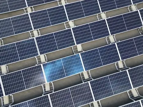
Perovskite and tandem lines re-route the same four-node control stack through different unit operations: SC SOLAR's 300 mm × 300 mm perovskite turnkey includes tank cleaning, plasma treatment, triple-chamber PVD (NiO/ITO/Cu), laser scribing (P1-P4), ALD (SnO2), and semi-auto lamination at 20-60 pcs/day [S4]. The 600 mm × 1200 mm variant scales to 150-450 pcs/day with vertical PVD and linear evaporation, with all-in-one coating and drying crystallization replacing the batch furnace steps used in silicon lines [S4].
The implication for process engineers: ALD and PVD bring new pressure and temperature operating points (sub-mbar chamber base pressure, lower thermal budget), while laser scribing adds a sub-millimetre alignment control loop that has no analogue in diffusion/PECVD silicon lines, which is why perovskite capacity is currently quoted in pieces-per-day rather than wafers-per-hour [S1][S4].
Process-Side Comparison: Sensor Technology on Each Node
On the irradiance node, thermopile pyranometers (ISO 9060 secondary standard, ±0.5% daily uncertainty) trade roughly 3 seconds of response time for spectral flatness, while silicon reference cells respond in microseconds but require temperature and spectral correction, making thermopile the plant-grade default and silicon the tracker-integrated head choice [S5]. On the electrical node, IV tracing delivers quantitative Pmax, EL delivers spatial defect maps, and hipot delivers insulation integrity, so the three are complementary, not interchangeable [S5]. On the thermal node, K-type thermocouples handle 320-420 °C reliably and cheaply, but Pt-100 RTDs win on long-term drift in the 140-160 °C lamination window [S5]. On the vacuum node, a Pirani or Baratron-style 0-1013 mbar absolute transmitter is the standard pick, and capacitance diaphragm gauges are the upgrade when ±0.1 mbar stability is needed for perovskite ALD load locks [S4][S5].
Selection Criteria and Sourcing Path
For a new 1 GW silicon cell line, the four-node instrument stack maps to roughly: one ISO 9060 Class A pyranometer per flash tester, one Class AAA solar simulator per stringer output, K-type TC on every solder station, and a 0-1013 mbar absolute pressure transmitter per laminator, with the 0.1 °C furnace temperature controller shared across the diffusion and PECVD tubes [S2][S5]. A standard, vendor-agnostic spec for a Class AAA flash tester is IEC 60904-9 spectral match, and the underlying IV trace calibration chain runs back to NIST or PTB-traceable reference cells [S5].
Tracking signals: (1) any new datasheet revision on horizontal batch PECVD that pushes on-wafer uniformity below 3% would be a step-change for next-generation TOPCon lines, and (2) the first commercial 600 mm × 1200 mm perovskite line at 450 pcs/day with closed-loop ALD pressure control will mark the point where perovskite capacity stops being quoted in pcs/day and starts being quoted in MW/year [S2][S4][S5]. For the inverter-side counterpart of this control stack, see the solar inverter process control instrumentation map.