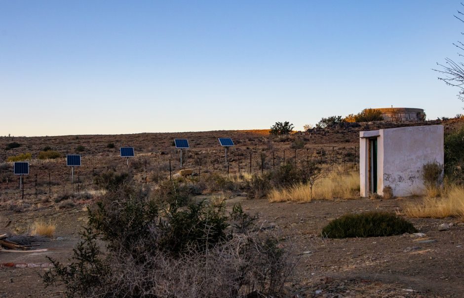
PV line instrumentation breaks into four measurement nodes — irradiance reference, cell electrical test, thermal profile, and lamination pressure/vacuum — and each node carries a distinct calibration chain back to a recognised metrology institute [S1].
Line-side control covers tabber/stringer temperature, IR/reflow belt speed, encapsulant lamination vacuum, and final module flash-test sorting, with the sensor layer feeding a PLC or SCADA that closes the loop on cell binning and string rework decisions [S1].
Irradiance Reference: Pyranometer, Pyrheliometer, and Reference Cell
Class A pyranometers (ISO 9060 secondary standard, ±0.5% daily uncertainty) and first-class pyrheliometers are the field reference for both production-line reference cells and outdoor PV plant monitoring, with thermopile and silicon-photodiode variants offered as the two main technology choices [S1].
Mounting options split into fixed-angle racks, single-axis trackers, and tracker-integrated sensor heads, while the output layer runs 4-20 mA, Modbus RTU, or SDI-12 to a data logger or plant SCADA; reference-cell packages typically add Pt-100 or thermistor temperature compensation at the cell body [S1].
Inline Cell and Module Electrical Test
Inline IV curve tracing, electroluminescence (EL) imaging, and ground-fault/hipot testers are the three standard electrical nodes inserted between cell coating, stringing, and final layup, with EL defect resolution typically specified at 0.2 mm/pixel or finer for hot-spot detection on shingled cells [S1].
A common spec pattern pairs a four-wire Kelvin sense on the cell probe bar with a 1000 V/8 mA EL bias supply, and the test data is binned by Pmax and fill-factor so the downstream stringer can grade cells into current-matched groups; for module-level sorting, a Class AAA flash tester (per IEC 60904-9 spectral match) closes the loop on nameplate wattage [S1].
Thermal Loop on Tabber/Stringer and Reflow Soldering

Tabber and stringer IR lamps hold solder zone temperature in the 320-380 °C window for Sn60Pb40 and 340-420 °C for lead-free SAC305, with a K-type thermocouple bead on the cell busbar providing the closed-loop signal to the PID controller; the same thermocouple is dual-redundant in higher-yield lines [S1].
Profiling of the reflow belt typically uses a 6-to-8 channel K-type profile thermocouple, with ΔT across the cell kept under 5 °C to avoid micro-cracking; HART or IO-Link transmitter heads allow the same sensor to land on either a legacy 4-20 mA DCS or a modern IO-Link master without rewiring [S1].
Lamination Stack: Vacuum, Pressure, and Encapsulant Cure
Laminator control is built around a heated-platen PID loop (setpoint 140-160 °C for EVA), a vacuum-pump pressure transmitter spanning 0-1013 mbar absolute, and a hydraulic or pneumatic ram pressure transmitter in the 0-10 bar range for the press cycle [S1].
The vacuum hold test (typically ≤50 mbar for ≥4 minutes) is the standard cure-quality check, and the same pressure transmitter that monitors pump-down also triggers the lamination cycle, so a drift above ±1 mbar absolute is a known false-pass risk for delamination [S1].
Process-Side Comparison: Sensor Technologies on Each Node
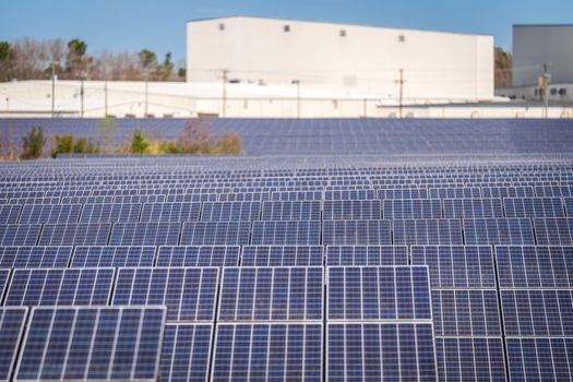
On the irradiance node, thermopile pyranometers trade response time (≈3 s slower) for spectral flatness, while silicon reference cells respond in microseconds but require temperature and spectral correction; for plant-grade monitoring, thermopile is the common choice, with silicon used on tracker-integrated modules [S1].
On the thermal node, K-type thermocouples are the default for tabber/stringer and laminator platen work below 600 °C, with Pt100 RTDs preferred on the encapsulant platen for ±0.3 °C accuracy, and IR pyrometers added as a non-contact backup where contact probes are not practical [S1].
Standards, Traceability, and Where the Stack Breaks
PV manufacturing QA pulls on IEC 61215 and IEC 61730 for module design and safety qualification, ISO 9060 for radiometer classification, and IEC 60904-9 for flash-tester spectral match class; pyranometer calibration chains run back to a national metrology institute through WMO-grade comparison [S1].
Line-side controls are typically built on a control valve stage for vacuum pump and hydraulic ram throttling, a multifunction process calibrator loop-check on the thermocouple and pressure transmitter channels during commissioning, and a fire alarm control panel tie-in only on lines that carry solvent-based flux or hot-air-knife exhaust; misalignment between lab-grade Class AAA flash data and production-line reference cells remains the most common cause of nameplate-binning dispute [S1].
Track the next move on the cell-process instrument side: the solar panel production capacity planning map for the 2026 MW-tier and cell-technology mix that drives how many inline EL and flash-test channels each new line needs, and the EV production line design spec map for the conveyor/IO-Link layout patterns shared between PV and battery gigafactories.