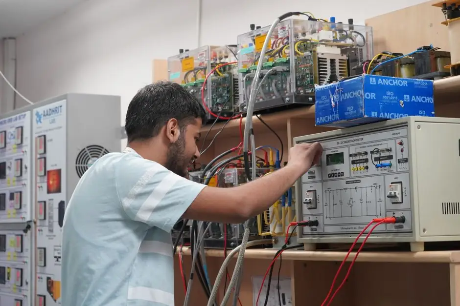
The start-inhibit function in a modern motor protection relay compares calculated thermal capacity used during a start attempt against a settable enable threshold, blocking the close command until the rotor and stator have cooled enough for a safe inrush [S2][S3].
In practice the relay runs a first-order thermal model: it integrates I²R heating during locked-rotor acceleration, bleeds heat back along an RC time constant when current drops to running levels, and exposes a TCU percent value that operators can read and trip against [S3].
How the TCU Calculation Works
The thermal element in a microprocessor-based protection relay treats the motor as a single thermal mass fed by a current-dependent heat source and drained by a first-order cooling path, so TCU is reported as a percentage from 0 (cold) to 100 (at or above rated run temperature) [S3]. During a start the relay integrates (I/Irated)² over the locked-rotor interval, adds the result to the prior TCU, and updates the displayed thermal register every cycle [S1][S3].
Cooling is split into two time constants in most relays: a stop time constant (motor de-energised, no fan airflow) and a run time constant (motor spinning, forced or self-ventilated airflow), with the stop constant typically several multiples of the run constant for totally enclosed fan-cooled machines [S3]. The start-inhibit logic is gated by a TCU enable threshold that the user dials in, separate from the trip threshold, so a process can be allowed to start at 70% TCU even though the trip element may be set to latch at 105% [S2][S3].
Slip-Based vs Simple I²t Thermal Models
Older electromechanical and early solid-state overloads protected motors by current alone, with no real thermal model and no start inhibit, while microprocessor relays can compare calculated TCU to a settable enable threshold to gate every close command [S1][S4]. The two model families in current production differ in how they handle the locked-rotor interval:
Slip-based models can auto-compute the maximum safe start time for each unique start sequence rather than relying on a single user-entered value, which cuts nuisance trips on long-acceleration loads [S1].
Setting the Enable Threshold: Practical Numbers
For medium-voltage motors covered by NEMA MG-1, the operating limit most engineers reconcile against the relay threshold is the number of consecutive cold starts (typically 2) and the number of consecutive hot starts (typically 1) the nameplate guarantees, with the thermal lockout set so that the relay blocks the second hot attempt until TCU has decayed into the safe-start band [S2]. The relay will still allow a cold start at any TCU below 100% if the user enables a cold-start override, but the override should be password-protected because it bypasses the thermal model the thermal relay depends on [S3].
Start Inhibit vs Trip: Different Functions, Same Model
Start inhibit is a permissive contact in series with the breaker close coil, while the thermal trip is a lockout that opens the breaker on overheat; both read the same TCU register, but they act at different thresholds and on different events [S3]. A clean settings table therefore lists TCU trip, TCU alarm, TCU start-inhibit enable, and TCU start-inhibit disable as four separate setpoints, with the disable value intentionally below the enable value to add hysteresis and prevent chattering near the threshold [S2][S3].
The thermal-overload block inside a motor starter is a different device class: a bimetallic or heater element plus mechanical trip that protects against soft faults such as mechanical overload, brownout, single-phasing and voltage unbalance, not against the locked-rotor heating that the relay's start-inhibit model is built for [S4]. Many packaged motor starters therefore ship with only the bimetallic overload and rely on an upstream microcomputer protection relay to provide TCU-based start inhibit, which is why a retrofit often adds the relay rather than replacing the starter [S3][S4].
What the Function Will Not Catch
TCU-based start inhibit does not detect a jammed load that the coupling shear pin has already released, because current collapses to near zero as the motor spins up unloaded and TCU never crosses the trip band [S3]. It also cannot flag a worsening bearing condition until vibration or current-spectrum sidebands reach the auxiliary inputs on a higher-tier relay; for those modes, vibration and motor-current-signature-analysis modules are added separately [S3].
For multi-start processes such as compressor anti-surge or pipeline pigging, a TCU-only scheme can over-block if the user sets the threshold too conservatively, and a better pattern is to combine TCU start inhibit with a minimum cooldown timer set from the run time constant, so a short, hot second start is rejected by the timer before TCU logic even runs [S2][S3].
Settings Derived from a Real Motor Data Sheet
For retrofit cases where the manufacturer has not published thermal data, the relay's pickup current is set to 1.05 to 1.10 times motor full-load amps, the rated run time constant is taken as the heating time constant from the motor's published thermal-withstand curve, and the stop time constant is set to 2 to 4 times the run constant for self-ventilated machines [S3]. The PCIC paper on motor-relay settings walks through worked examples for pipeline pumps and compressor drivers where the start-inhibit enable threshold is tuned to the process minimum restart interval rather than to a generic percent of TCU [S3].
A useful side benefit of the TCU register is that it gives operators a percent-of-heat number on the HMI, so the control room can see a motor sitting at 85% TCU and decide whether to schedule the next start, instead of waiting blindly for a cooldown timer to expire [S1][S3]. A related CT-loop sizing walk-through for small motor relays is laid out in Multi-turn primary CT loop for small motor protection relays, which pairs with this settings discussion when the relay sits downstream of a low-ratio CT.
Two trackable signals on 2026-10-06: more vendors are exposing TCU percent over Modbus/TCP and DNP3 so SCADA can trend thermal headroom, and relay firmware updates are adding per-phase TCU instead of a single averaged register, which improves accuracy on unbalanced supplies but raises the bar for current-transformer matching [S3]. For a wider view of how motor protection fits with other rotating-equipment controls, the Crane Anti-Sway and Positioning Automation: Sensor and Drive Stack piece shows the same thermal-modeling logic applied to crane hoist drives.