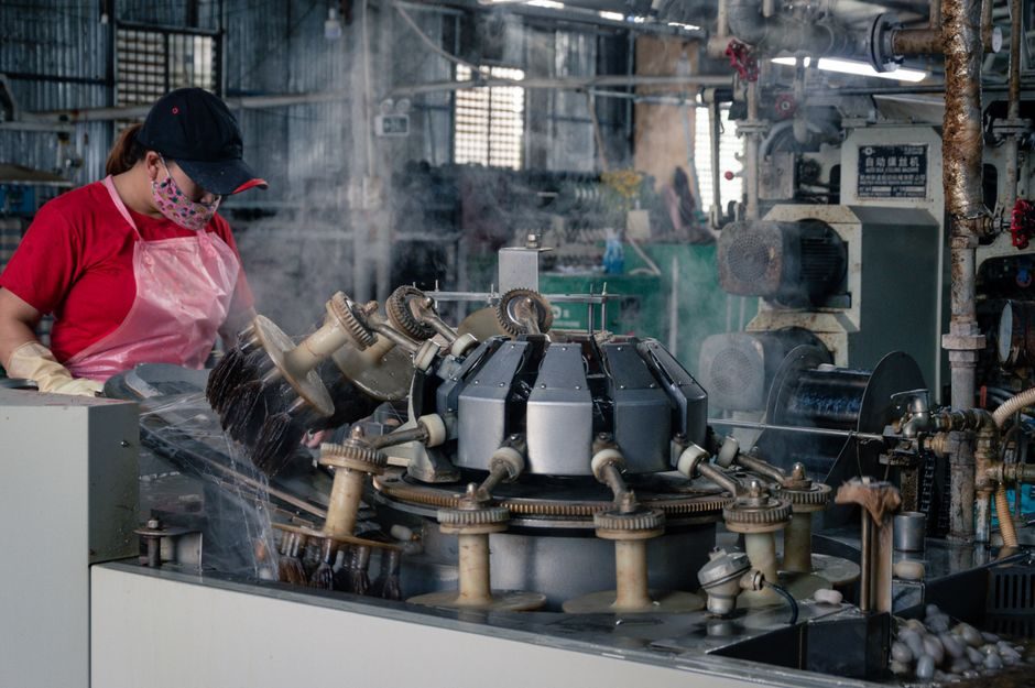
A steam trap is an automatic valve that releases condensate while preventing live-steam loss, and the wrong type costs both energy and process stability [S2]. A single failed trap can leak hundreds of pounds sterling per year, and an industrial steam network routinely carries several thousand traps, so the failure-rate gate matters as much as the size gate [S2].
Selection is governed by three numbers — maximum operating pressure, condensate load (kg/h), and discharge back-pressure — plus the service fluid (clean steam, process condensate, or dirty drainage). Read more on the device class in the steam trap encyclopedia entry.
Three Operating Principles Define the Shortlist
Mechanical, thermostatic, and thermodynamic traps are the three main groups, classified by which physical property actually opens the valve [S2]. Mechanical traps (float-ball, inverted-bucket) sense the density difference between liquid condensate and steam; thermostatic traps (bimetallic, balanced-pressure) sense the temperature gap; thermodynamic (disc) traps sense the velocity/kinetic-energy difference between flashing condensate and live steam [S2][S7].
That physics is not a marketing line — it dictates the failure mode. Bucket and float traps fail open (steam loss) when dirt jams the mechanism; thermostatic traps fail closed (stalled heating); disc traps tolerate water hammer and superheat but discharge cyclically and can be noisy on light loads [S2]. For a plant running mixed clean and dirty condensate, the rule of thumb is to isolate the duties and avoid one-trap-fits-all.
Pressure and Load: The Two Numeric Gates
Maximum working pressure (MWP) is the first elimination filter. Inverted-bucket and float traps cover low-to-medium pressure (typically under 16 bar); thermodynamic disc traps handle saturated steam across a much wider band and tolerate superheat; thermostatic bimetallic units are common on tracing lines under ~10 bar [S2][S5]. The trap body rating must equal or exceed the upstream saturation pressure at the design temperature.
Condensate load (kg/h) is sized at 1.5–2× the running load to absorb startup slugs. Sight glass and strainer upstream, check valve downstream on lifted returns, are standard accompaniments, and the sight glass should sit about 1 m from the trap outlet so operators can see the discharge [S2]. Skipping the strainer on a bucket trap is the single most common cause of jammed-float failures I've seen on chemical-plant surveys.
Comparison: Mechanical vs Thermostatic vs Thermodynamic
The decision matrix below lines the three families against four selection criteria that a buyer can actually score [S2][S7]:
1) Best pressure range: inverted-bucket/float 0.25–16 bar, thermostatic bimetallic/balanced-pressure 0–10 bar (clean steam/tracing), thermodynamic disc 0.25–250+ bar (saturated, superheat tolerant).
2) Tolerance to dirt/condensate contamination: float high (continuous water discharge), bucket medium (air-binding risk on startup), thermostatic low (sensitive to fouling), disc medium-high (self-clearing on cyclic discharge).
3) Failure mode: float and bucket fail open (steam loss), thermostatic fails closed (process stall), disc fails open but at lower leak rate due to small orifice.
4) Typical application: float for process heaters with steady load; bucket for intermittent or variable loads; thermostatic for steam tracing, drip, and clean-drip applications; disc for main headers, superheated lines, and outdoor duties where freezing risk exists [S2].
Who Should NOT Pick the Default Float Trap
Float traps are not the right default on superheated lines, on lines subject to freezing in winter, or on tracing where the load is too small for the float's minimum seal [S2]. Thermodynamic disc traps survive outdoor exposure because condensate freezing does not damage the disc; bucket traps, by contrast, must be insulated or specified as freeze-protected versions [S2]. If the return line lifts more than a few metres, add a check valve after the sight glass and before the riser — backflow will water-hammer a float chamber [S2].
For a broader selection context where steam quality upstream also matters, see the steam separator selection guide, which covers equipment placed in the same outdoor maintenance envelope.
Materials, End Connections, and Sourcing
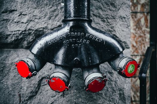
Body material tracks the corrosion duty. Carbon steel covers most plant steam up to ~425 °C; stainless steel (CF8 / 304, CF8M / 316) is the default for food, pharma, and clean-steam condensate; ductile iron is common on low-pressure HVAC drip lines [S6][S7]. End connections split between threaded (NPT/BSP) for sizes up to DN25 and flanged (ANSI 150/300) for DN40 and above; socket-weld shows up on high-pressure tracing manifolds.
On the sourcing side, OEM procurement data from 2026 shows Chinese float-trap offers clustered in the US$0.10–200 band per piece with 1-piece MOQ, versus branded OEM inverted-bucket units (Spirax-Sarco-pattern F&T/IB series) typically 3–10× the price of commodity floats at the same DN [S6][S7]. Factory-price gap of that scale is a real number, but a buyer who prices only on the unit is ignoring the lifetime energy loss — a leaking bucket can cost more in steam than the entire instrument. For a deeper dive on how downstream valve and gasket choices interact with the trap station, the needle valve selection criteria piece walks through the same pressure/seat-leak logic.
Commissioning, Monitoring, and the 3% Failure Gate
The performance benchmark an engineer should write into the spec is a station failure rate below 3%, which corresponds to about 3.6% of system energy lost through failed traps [S2]. Hitting that number takes two habits: a strainer before every trap with a documented cleaning interval, and a sight glass or ultrasonic survey programme on a fixed rota. On a 2,000-trap plant, a 3% failure rate is 60 leaking traps — at an average loss of several hundred pounds sterling per failed trap per year, the survey cost pays back in weeks [S2].
One more duty worth flagging: a trap specified for a process line should not be shared with a tracing drip line. The load swings are different, the pressure class usually is different, and the failure mode (open for process, closed for tracing) is the opposite — pick the right family per header, then sign off the MWP and load numbers per station.
Closing signal: a buyer choosing a steam trap should lock the MWP, condensate kg/h, and discharge back-pressure before looking at price, and ask the supplier for a documented failure-mode statement plus the matching strainer and check-valve BOM. Two trackable signals to watch on the next bid cycle are (a) the proportion of stainless CF8M versus carbon-steel bodies in OEM procurement, and (b) whether the supplier publishes a survey-and-replacement programme against the 3% failure-rate benchmark [S2].
For component-level specifications, see steam separator, and pressure transmitter.