A stepper motor choice collapses to four concrete gates before brand or vendor enters the conversation: holding torque, phase current, step angle, and frame size [S2][S5]. Holding torque for NEMA 17 motors typically lands in the 40-60 N·cm range with 1.2-2.0 A phase current and a 1.8° (200 steps/rev) step angle, which is why this frame dominates desktop 3D printers and light CNC gantries [S2].
Stepper motors run open-loop by default: every digital pulse advances the shaft by one fixed step, and position is inferred from pulse count rather than measured [S5]. This makes them mechanically simple and brushless, but it also means the drive system must be sized to prevent stall and lost steps under worst-case load [S5]. For a deeper primer on how stepper motors relate to the broader motor family, the stepper motor encyclopedia entry lays out the construction variants, while drive motor fundamentals cover how steppers sit next to servos in a controls architecture.
Frame Size and Torque Class: NEMA 17 vs 23 vs 34
Frame size sets the physical mounting pattern (inches) and the torque ceiling, so the first cut is mechanical: NEMA 17 (42×42 mm) covers roughly 40-60 N·cm holding torque and dominates FDM printers, laser galvos, and small pick-and-place axes [S2]. NEMA 23 (57×57 mm) typically delivers 1-3 N·m and is the workhorse for mid-size CNC routers and lab automation, while NEMA 34 (86×86 mm) climbs into the 3-12 N·m band for larger mills, plasma tables, and indexers [S2].
Step angle is the second cut: the de facto standard is 1.8° (200 steps/rev in full-step mode), and every speed calculation starts from there [S3][S5]. At 2000 steps/s the shaft runs at 600 RPM; double the step rate to 4000/s and you are at 1200 RPM until electrical limits intervene [S3]. 0.9° motors (400 steps/rev) exist for smoother low-speed motion but trade torque density and rarely beat a 1.8° motor plus 16× microstepping on the same axis [S3].
Driver Pairing: Current, Voltage, and the 5-10× Rule
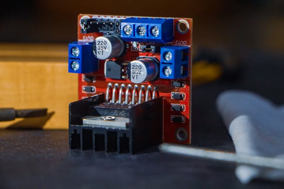
The driver must supply at least the motor's rated phase current continuously; under-speccing trips thermal shutdown, and over-speccing cooks the windings via I²R heating [S1]. A 2.8 A NEMA 23 needs a driver rated 2.8 A per phase or higher, and most A4988/DRV8825-class modules cap out around 2.2-2.5 A which is why closed-loop units like the uStepper S32 (up to 2.5 A) cover the vast majority of NEMA 17 and NEMA 23 builds [S1].
Supply voltage is a separate, equally important lever. The winding is an inductor, and at high step rates the current must slew fast enough to hit target before the next phase switch. The practical engineering rule is to run the driver at 5-10× the motor's rated voltage: a 2 A, 3 V motor performs better at 24 V than 12 V, provided the driver handles chopping regulation [S3]. Traditional drivers accept 8-35 V; closed-loop controllers like the S32 extend to 12-48 V, giving headroom for high-RPM CNC cutting and fast 3D printing moves [S1].
Microstepping is the third driver-side choice. Dividing each full step into 1/16, 1/32, or even 1/256 microsteps smooths low-speed motion and reduces resonance, with the S32 supporting up to 1/256 for very smooth precision work [S1]. The mechanical side of the same question is covered in the stepper drive encyclopedia page, which details current chopping and decay modes. Important caveat: microstepping does not raise absolute torque, and at high step rates the 16× and full-step curves converge because the driver has less time per microstep to regulate current [S3].
Open-Loop vs Closed-Loop: The Reliability Decision
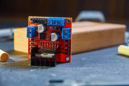
Open-loop drivers (A4988, DRV8825, TMC2209) are the cheap path and work fine for low-load, low-speed applications, but they cannot detect or recover from a lost step [S1]. A single missed pulse on a CNC mill means a scrapped workpiece; on a tall 3D print, it means eight hours of filament wasted. Closed-loop controllers add an encoder, verify position, and correct errors in real time [S1].
Cost reflects the choice: open-loop drivers run €2-10 per axis, closed-loop uStepper-class units are a larger line item, and a single scrapped part or troubleshooting day typically exceeds the price gap [S1]. The application rules of thumb in [S1] are concrete: 50-80 mm/s 3D printing is fine on TMC2209 in stealthChop, but 150+ mm/s or any production CNC router, mill, or engraver should move to closed-loop.
Speed Zones, Resonance, and Torque at Speed
Stepper motors have three speed zones with different dominant failure modes [S3]. 0-300 RPM is the low-speed band where resonance, cogging, and torque ripple dominate; 300-1000 RPM is the transition zone where winding L/R time constants fight the driver and back-EMF rises; above 1000 RPM the limit is inductive time constant and torque collapse [S3].
Torque drops with speed following the pull-out curve, and a motor holding 1 N·m statically might deliver only 0.3 N·m at 800 RPM [S3]. If the load needs 0.35 N·m to reach that speed in the available acceleration window, the rotor stalls. Acceleration itself follows T = J × α, so inertia matching is part of the spec, not an afterthought [S3].
When a Stepper Is the Wrong Tool
Stepper motors are cheaper and structurally simpler than servos, but servo drives cost more because they deliver higher dynamic performance, closed-loop accuracy, and far better high-speed efficiency [S4]. When the duty cycle demands continuous high RPM (above roughly 2000-3000 RPM with significant load), rapid acceleration reversals, or sub-arc-minute positioning with measurable disturbance rejection, a servo or AC motor solution will beat a stepper on throughput and energy use [S4]. For a fuller side-by-side, the drive motor comparison covers torque density, efficiency, and feedback trade-offs.
For very high force in a small envelope, a linear motor is the right answer; for high-torque, low-rpm rotary motion in heavy machinery, a hydraulic motor often wins on power density. The stepper sweet spot stays narrow: open-loop simplicity, moderate speed, full torque at standstill, predictable digital positioning [S5].
Selection Checklist and Shortlist Logic
Run this gate sequence before quoting a vendor: (1) compute load torque at operating speed and apply a 1.5-2× safety margin; (2) pick the smallest NEMA frame that meets that torque with the desired step angle, defaulting to 1.8° [S2][S5]; (3) match driver phase current to motor rating and driver supply voltage to 5-10× motor voltage [S1][S3]; (4) decide open vs closed loop using the 50-80 mm/s and 150+ mm/s breakpoints plus CNC duty [S1]; (5) verify microstep resolution against smoothness need, defaulting to 16× unless a specific accuracy target demands more [S1][S3].
For buyers sourcing 3D printer or CNC gantries in volume, the 3D printing procurement spec-first playbook translates these same gates into RFQ language, while bearing demand 2026 to 2030 is a useful cross-check on lead screw and linear-guide pairing for the same axes. Trackable signals worth watching through 2026: closed-loop controller pricing at the €30-50 mark for sub-3 A NEMA 23 duty, and driver chips delivering 48-60 V bus support at sub-€15 unit cost; either shift pulls the open vs closed-loop crossover down by a frame size.