
Time relays and relay modules sit in the same DIN-rail wiring space but solve different problems: a time relay carries its own timing engine and contact rating, while a relay module is a low-power switch matrix that inherits both timing and logic from an upstream controller [S2][S5].
Specifying the wrong one wastes panel space, misallocates cost, and forces a redesign when the certification audit shows the timing function is not properly anchored. The two products are listed as separate product families on the same manufacturer's catalog (NCR Industrial, 2026) — Time Relay sits next to Relay Module & Socket, with annual factory output over 100 million pieces across the combined relay family [S2].
Definition and Functional Scope
A time relay is a self-contained timing device: it accepts a trigger input, runs an internal RC or digital timer (on-delay, off-delay, flasher, star-delta, and similar modes), and switches its output contact when the preset expires. Off-the-shelf modules such as the DC5V/12V/24V 10A 32-mode trigger timer on the open market expose 32 timing modes in a single SKU at roughly US$3.73 retail, showing how compressed the timing-function market has become [S3]. Hongfa's "Time Relay Module" product group on its 2026 product page explicitly bundles the time relay with the relay module form factor, reflecting a market where the two are increasingly co-specified [S5].
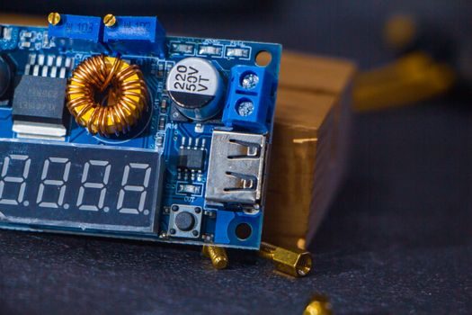
A relay module is a board-level assembly — typically one or more electromagnetic relays on a PCB with coil-driver transistors, flyback diodes, status LEDs, and header or screw terminals. The HW-307 module used in the digi-relay GitHub project (2024) is a textbook example: 5V coil, single-pole output, opto-isolated in some variants, with timing logic implemented in the upstream Digispark Tiny85 MCU, not in the module itself [S1]. Modules multiply channel count (4-channel, 8-channel, 16-channel are common SKUs) but add zero timing intelligence on their own.
Decision Criteria: When to Use Which
Use a time relay when any of these is true: the timing function must survive controller failure, the panel needs a third-party-certified timing path (UL/CE/IEC 61810 for the contact block), the operator needs a local potentiometer or digital setpoint to adjust delay without reprogramming, or the timing requirement is documented as a safety or process interlock. A time relay's contact block is the rated switching element — typically 5A to 10A resistive at 250VAC for the 32-mode consumer-grade timer module, with industrial lines reaching 16A and above [S3][S5].
Use a relay module when timing is already implemented in the PLC/MCU firmware, when you need more than four channels in a small footprint, when the wiring is 24VDC logic-level, or when cost-per-channel dominates. A 4-channel Raspberry Pi relay module (Instructables, 2026) is the canonical maker example: timing is provided by the Pi, switching is provided by the module, and the assembly lives in a 5V logic world [S4]. For panel builders, the same logic applies to a PLC sinking-output card driving an 8-channel module — the relay is the muscle, the controller is the clock.
Comparison Matrix: Time Relay vs Relay Module
Across four procurement-relevant criteria, the two product families diverge sharply. (1) Timing source: time relay is internal (potentiometer, digital set, or DIP modes); relay module is external (PLC, MCU, SBC) [S3][S1]. (2) Contact rating: time relays commonly spec 5A–10A at 250VAC on the consumer/light-industrial tier and up to 16A on industrial lines; relay modules typically spec 10A at 125VAC or 30VDC per channel, with the aggregate limited by PCB trace and terminal block [S3][S5]. (3) Channel density: a time relay is almost always 1 output (some dual-time SKUs exist); a relay module is commonly 1, 2, 4, 8, or 16 channels on one board [S4]. (4) Certification footprint: a time relay ships as a finished control component with its own UL/CE/IEC 61810-1/EN 61810-1 marking on the timing block; a relay module often ships as a "functional module" with CE only at the board level, leaving system-level compliance to the integrator. Encyclopedia-level detail on the time relay versus relay module families is catalogued separately for this reason.
Use Cases and Wiring Examples
A real-world wiring case published on GitHub (October 2024) shows why a controller plus relay module sometimes has to be augmented with a separate timing path: a Hikvision DS-KV8113-WME1 door station held its trigger closed for at least 1 second, but a Nice Robus 600 gate automation needed an SBS (step-by-step) pulse of 0.4–0.8 second. The fix was a Digispark Tiny85 driving an HW-307 relay module to re-time the closure — a 5V logic-level relay module used as the output stage of a software-defined time relay [S1]. That same job, in a panel, is a one-part time relay with an adjustable on-delay set between 0.4s and 0.8s. The choice is integration effort vs BOM count.
For home-automation and small-batch control, the 4-channel Raspberry Pi relay module (Instructables, 2026-05) is the dominant pattern: Python schedules timing, GPIO drives the module, the module switches 230VAC loads. For panel builders specifying industrial relay sockets alongside timers, NCR's 2026 catalog lists "Time Relay" and "Relay Module & Socket" as distinct product lines with separate datasheets, so the procurement code and the on-panel footprint differ even when the underlying contact physics is shared [S2].
Failure Modes, Limits, and Sourcing Signals

Time relays fail predictably: electrolytic timing-cap drift shifts the setpoint over years, mechanical contacts wear at the published resistive/inductive rating, and the timing mode (on-delay vs off-delay vs flasher) must be re-selected after any power reset on electromechanical models. Relay modules fail differently: coil-driver transistor failure, flyback-diode omission on DC coils (back-EMF destroys the upstream MCU), and shared-terminal overcurrent when multiple channels switch simultaneously. For a deeper look at the safety-side cousin, see the safety relay family, which adds force-guided contacts and is not interchangeable with a general-purpose time relay. [S2]
Sourcing signals as of 2026-08: NCR Industrial (Wenzhou/Jiaxing, two factories, 600+ staff, 100M+ pieces/year) lists Time Relay and Relay Module & Socket as separate product lines with separate download packages [S2]; Hongfa's product page (2026-06) explicitly groups "Time Relay Module" as a hybrid SKU for OEM integration [S5]; the open-market 32-mode timer module at US$3.73 indicates the consumer-tier price floor has not moved materially since 2025 [S3]. For spec-first decision matrices on related components, the relay module selection criteria map and the remote I/O spec gates article cover adjacent procurement territory. A trackable next signal: IEC 61810-1 revision activity and EN 61810-1 updates typically re-rate contact endurance for time relays on a multi-year cycle — confirm the latest revision cited in any 2026 datasheet before locking the BOM.